Location:Home Page > Archive Archive
3 steps to teach you how to analyze a buck chain
2023-12-05【Archive】
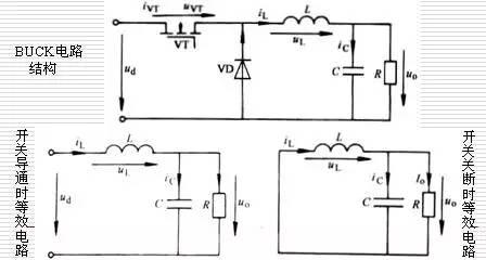
1. Basic Structure of BUCK Schema
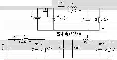
Equivalent circuit with switch on Equivalent circuit with switch off
2. Equivalent circuit model and basic laws
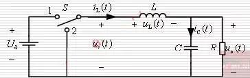
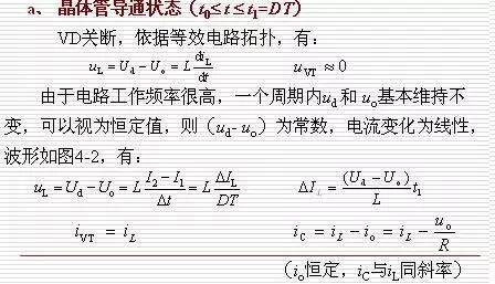
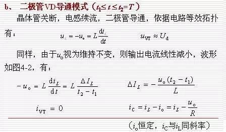
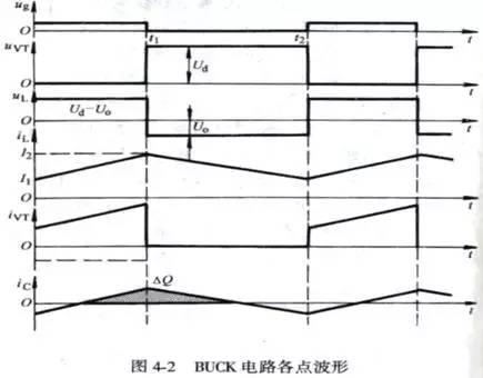
(1) It can be seen from diagram that inductance L and capacitance C form a low-pass filter. The principle of this filter design is to allow DC component us(t) to pass and suppress harmonics us(t) The component passes, output voltage uo(t) across capacitor is DC component us(t) plus small ripples uripple(t) .
(2) The operating frequency of circuit is very high, and ripple uripple(t) caused by charging and discharging of capacitor in one switching cycle is very small,
Regarding DC output voltage Uo across capacitor: 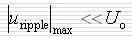 The voltage on capacitor macroscopically can be considered constant. When circuit is operating in steady state, voltage across output capacitor is composed of tiny ripples and a large DC component, which macroscopically can be considered as a constant DC current. This is principle of approximation of small ripples in steady state. analysis of switching circuits. (3) When charge charge of capacitor is higher than discharge charge in one cycle, voltage of capacitor increases, resulting in a decrease in charge charge and an increase in discharge charge in next cycle. , which slows down rise in voltage across capacitor. This process continues until charge-discharge balance is reached, and voltage at this time remains unchanged; on contrary, if discharge charge in one cycle is higher than charge charge, it will cause charge charge to increase and discharge charge to decrease in subsequent cycle, slowing down voltage drop across capacitor. This process continues until balance of charge and discharge is reached, and finally voltage will remain constant. This process is voltage regulation transient of capacitor. When circuit is in steady state, circuit reaches a stable balance, and charge and discharge of capacitor also reach balance. This is a general law when circuit is in steady state. (4) When switch S is set to 1 position, inductor current increases and inductor stores energy, and when switch S is set to 2 positions, inductor current decreases and inductor releases energy. Assuming that increase in current is greater than decrease in current, increment in flux on inductor per switching cycle is:
 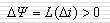 此增量将产生一个平均感应电势:
  This potential will reduce rate of rise of inductor current and at same time reduce rate of fall of inductor current, which will eventually cause average increment of inductor current to be zero per cycle; condition that flux linkage increment on inductor for one switching cycle is less than zero is same. This phenomenon, in which average increment of current of inductor (the average increment of flux linkage) is zero in a cycle under steady conditions, is called: volt-second balance of inductor. This is another general law of steady operation of power electronic circuits.
3. Analysis of inductor current in continuous operation
→ Analysis of a steady workflow in continuous operation mode (CCM)
Related
- 3 steps to teach you how to analyze a buck chain
- Three circuit diagrams to teach you how to understand how a buck RC works
- 3 MOSFET device selection rules that will teach you how to become a device selection wizard
- How to choose a suitable power chip, do you know this?
- Control Loop Design Solution, 5 steps to tell you
- How to distinguish induction from leakage, we will teach you three tricks! Ordinary people can also learn super practical
- How to design a triode amplifier circuit
- How did BUCK scheme come about? Application: 3 kinds of evolutionary chains
- How to solve the problem with electrostatic discharge? Use several real cases to conduct a joint analysis
- How to Calculate Inductance of a Transformer in One Article
Hot Posts
 How to distinguish induction from leakage, we will teach you three tricks! Ordinary people can also learn super practical
- What is drowning in gold? Why Shen Jin?
- This is a metaphor for EMI/EMS/EMC that can be understood at a glance.
- How many types of pads have you seen in PCB design?
- Summary of Common PCB Repair Techniques
- What is three anti-paint? How to use it correctly?
- Knowing these rules, you will not get confused looking at circuit diagram.
- How to make anti-interference PCB design?
- Can diodes do this?