Location:Home Page > Archive Archive
Why did your 4.7uF capacitor become 0.33uF? too weird
2023-03-18【Archive】
A few years ago, after more than 25 years of experience with ceramic capacitors, I re-evaluated them. At time I was busy working on an LED light bulb driver and apparently there was a problem with RC circuit time constant in my project.
My first hypothesis was that something on board was misjudged, so I measured two resistors used as a voltage divider and they were fine. I removed capacitor from PCB and measured it and there was no problem. To confirm further, I measured and installed new resistors and capacitors, powered up circuit, checked if it was working properly, and then saw if replacing components fixed problem with RC circuit's time constant. But no.
I tested circuit in its natural environment: inside case, with circuit inside case, simulating a "pot" of roof lighting, with components sometimes heated to over 100 degrees Celsius. Although I had quite a bit of time to re-test RC circuit, it was still very hot to touch.
Obviously my next conclusion is that problem is change in temperature of capacitor. But I myself doubt this conclusion, because. I use X7R capacitors. According to my memory, this capacitor can work up to +125°C, and difference is only ±15%. I trust my memory, but just in case of a side, I re-checked datasheet for capacitor used.
General report
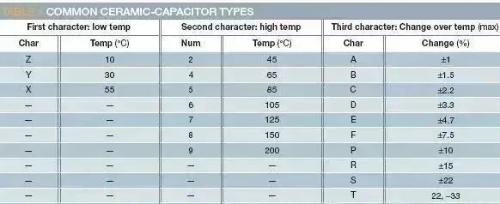
Table 1 shows letters and numbers used for different types of ceramic capacitors and their respective meanings. The table describes class II and class III ceramic capacitors. Without going into details, we note that class I capacitors include common type COG (NPO).
This capacitor is not as volume efficient as two capacitors in table, but it is much more stable under various environmental conditions and is not subject to piezoelectric effects. In contrast, capacitors in table have widely varying characteristics, being able to expand and withstand applied voltage, but sometimes produce an audible piezoelectric effect (buzzing or ringing).
In my experience, among various types of capacitors, most commonly used are X5R, X7R and Y5V. I have never used Y5Vs because they exhibit extreme capacitance fluctuations under varying environmental conditions.
When capacitor manufacturing companies design products, they choose characteristics of material so that capacitor can operate within a certain range of variation (third letter; table 1). I use X7R capacitors that do not change more than ±15% between -55°C and +125°C. So, either I'm using a bad batch of capacitors, or there's something else wrong with my circuit.
Not all X7R capacitors are same
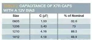
Since problem with my RC circuit's time constant cannot be explained by a specific temperature variable, I need to dig deeper. Looking at capacitance and applied voltage data of my capacitor, I was surprised to find that capacitance varies so much with tuning conditions. I chose a 16V capacitor that operates at 12V bias. The datasheet says that my 4.7uF capacitors typically provide 1.5uF capacitance under these conditions. Now RC circuit problem can be fully explained.
The datasheet shows that if I increase size of capacitor from 0805 to 1206, typical capacitance under these conditions is 3.4uF. This indicates need for further research.
I've found that Murata and TDK provide some nice tools on their website that can display capacitance change under various environmental conditions. I did some research on 4.7uF capacitors of various sizes and voltage ratings. The data in Figure 1 is taken from Murata's tool for several different 4.7uF ceramic capacitors. I observed models X5R and X7R with package sizes from 0603 to 1812 and nominal DC voltage from 6.3 to 25V. I first noticed that as package size increased, change in capacitance with applied DC voltage decreased, and magnitude is very large. .
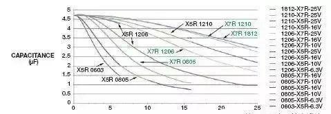
Figure 1 This figure shows relationship between DC voltage across a selected 4.7uF capacitor and temperature change. As shown in figure, as package size increases, capacitance decreases significantly with applied voltage.
CAPACITY (µF) DC VOLTAGE (V) DC Voltage (V) The second interesting point is that for a given case size and type of ceramic capacitor, voltage rating of capacitor is generally not affected.
So, I calculated that if a capacitor with a nominal voltage of 25 V is used for a voltage of 12 V, change in capacitance will be less than that of a capacitor with a nominal voltage of 16 V under same conditions. Looking at curves for X5R in 1206 package, it's clear that 6.3V rated components do outperform their higher rated counterparts.
If we look at a wider range of capacities, we can see that this is very common. The capacitor sample sets I studied did not show expected behavior of conventional ceramic capacitors.
The third problem I've noticed is that in same package, X7R capacitors are more temperature sensitive than X5R capacitors. I don't know if this is true in general, but in my experiments it seems to be case.
As you can see from figure, Table 2 shows decrease in capacitance of X7R at 12V bias. Note that there is a constant increase in capacitance as capacitor size is increased up to 1210, but little changes after this size.
Choose right capacitor
In my example, I chose smallest package available for 4.7uF X7R capacitor, because size was taken into account in my design. In my ignorance, I assumed that any X7R would have same effect as any other X7R; obviously it is not. In order to get right performance for my application, I have to use some larger package.
I really don't want to use 1210 package. Luckily, I was able to increase value of resistor used by 5 times, thus reducing capacitance to 1uF.
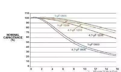
Figure 2 is a voltage characteristic diagram of several 16V, 1uF X7R capacitors and 16V, 4.7uF X7R capacitors. The 1uF capacitor 0603 behaved same as 4.7uF capacitor 0805. The 1uF capacitor on 0805 and 1206 performed slightly better than 4.7uF capacitor 1210. So with 1uF capacitors from 0805 I can keep volume of capacitor same and when biased capacitor only drops to 85% of its rated value, not 30%.
But I'm still confused. I used to think that all X7R capacitors should have same voltage factor because dielectric used is same, all X7R So I asked a colleague, Chris Burkett, application engineer at TDK Japan, who is also a ceramic specialist at Chip Capacitors .
He explained that many of materials would qualify as "X7R". In fact, any material can be referred to as X7R if it allows device to meet or exceed X7R temperature rating (i.e. -55°C to +125°C with ±15% variation). . Burkett also clarified that there is no specific voltage factor specification for X7R capacitors or any other type of ceramic capacitor.
This is a key point, so I'll repeat it. Manufacturers can call a capacitor an X7R (or X5R, or whatever) capacitor as long as it meets temperature coefficient specification, no matter how bad its voltage coefficient is. This fact confirms mantra (pun intended) that any experienced electrical engineer knows: read datasheet!
As manufacturers move to smaller components, they have to compromise on materials used. In order to achieve required volumetric efficiency with smaller dimensions, a worse voltage factor had to be adopted. Of course, reputable manufacturers will minimize side effects of this compromise.
The conclusion is that reading datasheet is extremely important when using ceramic capacitors in small packages (in fact, when using any component). Unfortunately, often specifications we see are brief and contain little to no information needed to make a decision, so youyou have to insist on obtaining additional information from manufacturer.
What about Y5V capacitor that I denied? For sake of interest, let's examine usual capacitor Y5V. I chose a 4.7 uF, 6.3 V base in a 0603 package) I will not name manufacturer, since its Y5V base is not inferior to Y5V base of any other manufacturer) and looked at it at 5V and + 85 ° Specifications under C. At 5 The typical capacitance is 92.9% below nominal or 0.33uF.
That's right. If a 5V bias is applied to this 6.3V capacitor, its capacitance will be 14 times less than nominal value.
At a 0V offset of +85°C, capacitance decreases by 68.14%, from 4.7uF to 1.5uF. You might think that with a 5V bias, capacitance drops from 0.33uF to 0.11uF. do not combine in this way. In this particular case, change in capacitance at room temperature at a bias of 5V is worse than at +85°C.
Specifically, capacitance of this capacitor will drop from 4.7uF at room temperature to 1.5uF at +85°C at 0V bias, and increase from 0.33uF at room temperature to 1.5uF at 5V bias V. 0.39uF at +85°C. This result should convince you that it's really worth looking into specifications of components.
Get started on details
After this tutorial, I will never again recommend certain X7R or X5R capacitors to my colleagues or consumers. I would recommend them a component from a vendor whose data I checked. I also remind consumers to be sure to check data when considering alternative product suppliers so that they do not run into my problems.
Perhaps you have learned main lesson: read datasheet every time without exception. If there is not enough information in data sheet, ask manufacturer for specific data. Also remember that naming of ceramic capacitors, X7R, Y5V, etc., has nothing to do with voltage ratio. Engineers must study data to know (really know) how a particular capacitor will perform at that voltage.
At end of day, remember that as we continue our frantic pursuit of smaller sizes, this has also become a daily issue.
Related
- Why did your 4.7uF capacitor become 0.33uF? too weird
- What is purpose of connecting a polar capacitor and a non-polar capacitor in parallel?
- Suggested collection: Capacitor filtering analysis and EMC suggestions.
- The size, withstand voltage and direction of capacitor, how to choose these parameters?
- Four leg inductor? Did you see it?
- step-down capacitor pay attention to these six points, do not need to worry about circuit analysis
- Engineer Daniel tells you: The "Y Capacitor" of a switching power supply is calculated in this way.
- Did you pay attention to details of using relay?
- Why do LED bulbs get dimmer the more they are used? Why is it flickering?
- How did BUCK scheme come about? Application: 3 kinds of evolutionary chains
Hot Posts
 How to distinguish induction from leakage, we will teach you three tricks! Ordinary people can also learn super practical
- What is drowning in gold? Why Shen Jin?
- This is a metaphor for EMI/EMS/EMC that can be understood at a glance.
- How many types of pads have you seen in PCB design?
- Summary of Common PCB Repair Techniques
- What is three anti-paint? How to use it correctly?
- Knowing these rules, you will not get confused looking at circuit diagram.
- How to make anti-interference PCB design?
- Can diodes do this?