Location:Home Page > Archive Archive
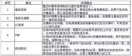
Suggested collection: Capacitor filtering analysis and EMC suggestions.
2023-03-26【Archive】
01
Capacitor filtering effect
That is, higher frequency f, lower impedance Z of capacitor.
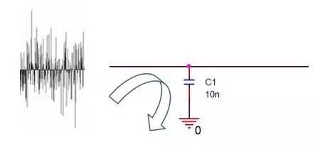
At low frequency, due to relatively large impedance Z of capacitor C, useful signal can pass unhindered;
At high frequency, capacitance C is already very small due to impedance Z, which is equivalent to short circuiting high frequency noise to GND.
02
When will capacitive filtering stop working?
Rectifiers often use components such as capacitors for filtering. It is often said that "large capacitors filter low frequencies and small capacitors filter high frequencies".
Let's take a conventional MLCC surface mount ceramic capacitor as an example. The equivalent model looks like this:
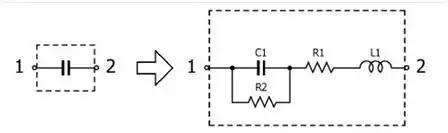
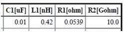
The parameters of X7R ceramic model with a capacitance of 10 nF in 0603 package are as follows:
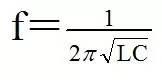
Because equivalent model has both capacitance C and inductance L, forming a second-order system, instability occurs. The circuit is in resonance and resonance point is at following frequency:
The image below shows an example of a resonance curve:
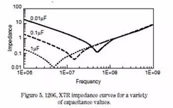
That is, it is a capacitor before resonance point and no longer a capacitor after resonance point.
03
When to use LC filter
If an inductor L is connected in series and then connected in parallel to form C, an LC filter is formed:
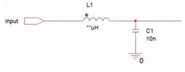
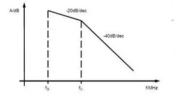
One capacitor C is a first order system and one inductor L is also a first order system, and slope of attenuation amplitude is -20dB. However, for a second-order system composed of LC, attenuation amplitude slope is -40 dB, which is closer to ideal "steep" cutoff frequency effect, i.e., filtering effect is better.
04
What is PWM frequency
PWM is often mentioned, for example, 20kHz PWM is used to drive a motor. But in fact, these 20 kHz only mean that PWM pulse period is 50 µs:
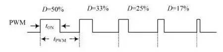
Then where frequency point of so-called PWM of 20 kHz falls into frequency domain, following formula:
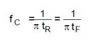
For a step signal, since rise time tr is infinitely short, frequency f is infinitely large. When frequency is high, parasitic parameters cannot be ignored, which will cause many resonance problems.
From a signal point of view, a signal with a very steep pitch will have problems with overshoot and wobble. Simply put, larger frequency f, wider frequency occupied by noise will be, i.e. worse EMC performance will be.
05
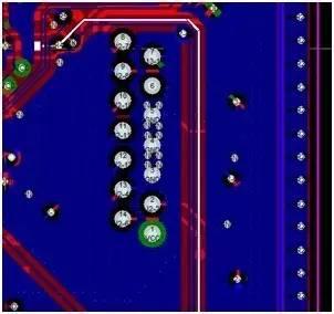
How to map a circuit diagram to a PCB
Due to problem of separation of work types, schematic diagram and PCB were separated, and division of work was carried out by two groups of people:

For example, circuit diagram has following diagram:
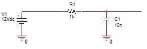
This means that problem is that there is actually a line between negative pole V1 and negative pole C1 on PCB (the word used in PCB layout software is more accurate: trace, trace/trace ).
A->B->C are often affected during design phase. If there is a problem with EMC, in addition to searching for circuit parameters on circuit diagram, you also need to pay special attention to C->D, that is, return path.
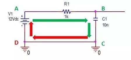
If return path is uneven, it will distort signal:
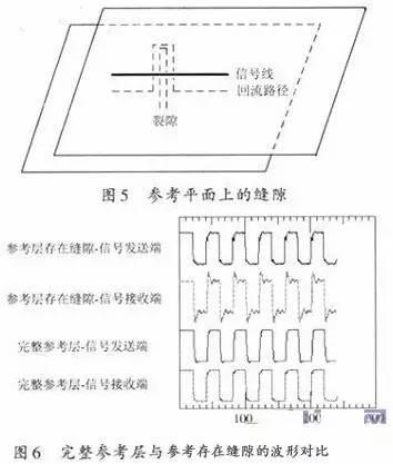
For example, during an EMC test, if signal collected by ADC of microcontroller is broken, in addition to analyzing it on circuit diagram, highlight signal on board, and then patiently look for return path of signal. Uneven places:
06
Summary
Related
- Suggested collection: Capacitor filtering analysis and EMC suggestions.
- Senior EMC Engineer Resume: EMC Troubleshooting Process and Common Problems
- What is purpose of connecting a polar capacitor and a non-polar capacitor in parallel?
- Diagram of relationship between PCB layout and EMC
- step-down capacitor pay attention to these six points, do not need to worry about circuit analysis
- PCB design guidelines: safety regulations, layout and wiring, EMC, thermal design, process engineering.
- The size, withstand voltage and direction of capacitor, how to choose these parameters?
- ADC basics and comparative analysis of different ADC technologies
- Haberdashery|General failure mechanism and analysis of electronic components
- Analysis and comparison of 6 most commonly used DC power supply circuits
Hot Posts
 How to distinguish induction from leakage, we will teach you three tricks! Ordinary people can also learn super practical
- What is drowning in gold? Why Shen Jin?
- This is a metaphor for EMI/EMS/EMC that can be understood at a glance.
- How many types of pads have you seen in PCB design?
- Summary of Common PCB Repair Techniques
- What is three anti-paint? How to use it correctly?
- Knowing these rules, you will not get confused looking at circuit diagram.
- How to make anti-interference PCB design?
- Can diodes do this?