Location:Home Page > Archive Archive
What is purpose of connecting a polar capacitor and a non-polar capacitor in parallel?
2023-03-18【Archive】
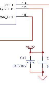
The circuit diagram is drawn as a polar capacitor and a non-polar capacitor connected in parallel, more for purpose of adding appropriate contact polarity information to PCB silkscreen layer during drawing board process, to avoid incorrect connection of polar fried capacitor.
Of course, older EE drivers can usually see right away that this is a classic PSU decoupling capacitor combination. An ideal power supply should provide a stable constant voltage, so object of decoupling is interference in power supply network. Installing a capacitor in power supply to ground is simplest solution to this problem.
As to why it's a strange form of polarity//non-polarity, instead of choosing polarity//polarity or outright choosing a capacitor of equivalent capacitance, it makes little sense.
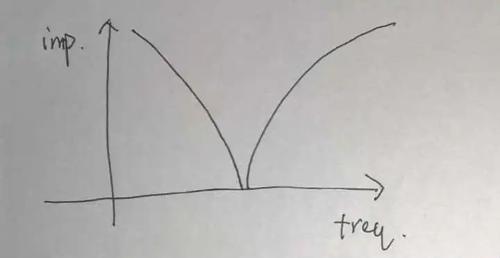
Generally speaking, large-capacity polar capacitors in a real circuit will be electrolytic capacitors, and small-capacity non-polar capacitors will be ceramic capacitors, and like. For an ideal capacitor, turn-off frequency curve is as follows.
This is also impedance characteristic that an ideal power supply network should have. The actual capacitor will have an equivalent series inductance (ESL) due to contact and inherent characteristics of material, which is why curve becomes so ghostly.
The capacitance of electrolytic capacitor is very large, but at same time, ESL is also very large, so it is used for decoupling at low frequencies. But in high-frequency range, due to large ECL, “inductive characteristic” of electrolytic capacitor dominates at this time, and higher frequency, weaker decoupling effect. Sometimes circuit uses high capacity electrolytic capacitors to smooth out voltage fluctuations in extremely low frequency ranges. At this time, energy storage characteristics of capacitors are used to a greater extent (you can also pay extra for linear regulators to solve this problem), rather than "decoupling" or "filtering ' in narrow sense.
Although capacitance of ceramic capacitors is small, decoupling effect in low frequency range is not obvious, but relatively small ESL provides a very good decoupling effect in a certain range of high frequency bands.
Therefore, it is best to use these two capacitors in parallel. Taken together, the impedance curve will look something like this.
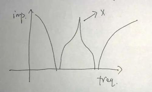
The impedance curve of this ideal capacitor model is very odd because ESR is ignored, with spikes and negative impedance. Given phase-frequency characteristics of impedance, this combination of circuits may even resonate when impedance is close to zero. Therefore, in order to investigate this problem, it is necessary to add ESR of capacitor, for example, circuit in following form.
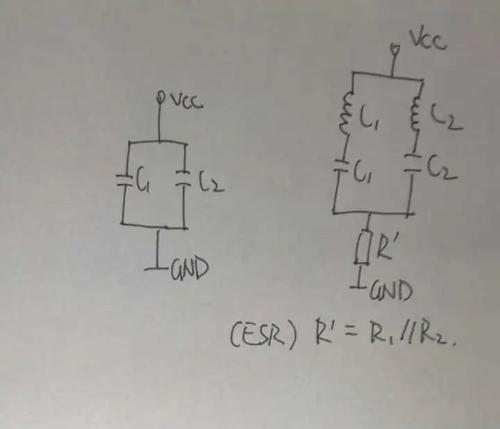
Then the impedance characteristic will be like this.
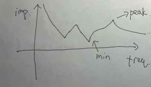
As shown in figure above, although impedance characteristic curve also has sharp peaks and valleys, overall it is obviously much smoother than in figure above. The peak part is usually referred to as "anti-resonant" point (anti-resonance). Since a combination of capacitors is required to fulfill decoupling role, one of design considerations is that this peak should be far from lumped point of noise frequency distribution in circuit. The idea behind using this peak in reverse order is to place this peak as close as possible to frequency concentration point of adjacent load's current spectrum in order to minimize effect of changes in adjacent load on circuit topology on local voltage.
The REF pin is connected to decoupling circuit on circuit diagram of item, which is usually related to reference signal input. Without further information, I'll just assume a scenario illustrating significance of valleys in chart above. Assuming this is REF pin of ADC, ADC will draw current from REF pin one or more times per conversion cycle, depending on design of ADC circuit. In this case, current RZP spectrum is regular. We hope that voltage at REF pin fluctuates as little as possible during operation, so valley of decoupling network can be as close as possible to frequency concentration point in current spectrum. Because min value is smaller than ESR R' value, mains impedance to current signal is lowest at this frequency. This is second design point.
Here one more problem should be mentioned, namely potential danger of resonance created by decoupling network. Although minimum decoupling impedance value is no longer zero after ESR is taken into account, in many circuits this minimum value is still quite low. Combined with fact that other end of decoupling network is power supply, minimizing chance of resonance has become almost a standard design rule. As for how to eliminate resonance, this is another difficult topic.
Summarizing, we can say that parallel connection of different types of capacitors, one large and one small, can be easily explained by method of "matching high and low." But strictly speaking, especially for simple digital circuits, current spectrum has obvious rules during workflow. Compared to a structure using a single capacitor, combination of two capacitors in parallel provides a lot of room for optimization under condition of optimal cost. (one large and one small combination of ESR and ESL).
The above is generally in theory, but in practice it is very difficult to make such an optimization. The main reason is that there are too many parameters in circuit that affect ECL, and a serious discrepancy between “constitution” of cheap electrolytic capacitors makes analysis of ECL discrepancy very difficult. RezThe last sentence is that it is difficult to compare results of theoretical calculations with constructed scheme.
What about current spectrum of a circuit that has no obvious frequency distribution? The easiest way is to use more capacitors with different parameters and materials from different specifications so that this characteristic curve constantly approaches "flat state" of design requirements.
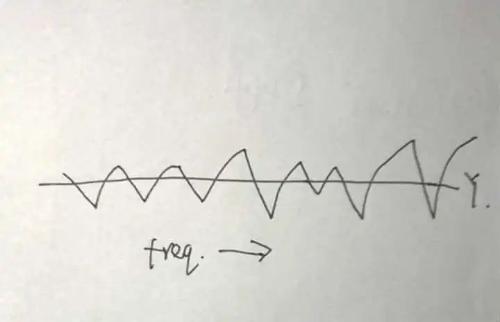
Power Integrity is a systematic study of such problems.
Related
- What is purpose of connecting a polar capacitor and a non-polar capacitor in parallel?
- The role of polar and non-polar capacitors in parallel connection
- Engineer Daniel tells you: The "Y Capacitor" of a switching power supply is calculated in this way.
- The size, withstand voltage and direction of capacitor, how to choose these parameters?
- What is a magnetic sensor? The most common types of magnetic sensors and their applications
- Suggested collection: Capacitor filtering analysis and EMC suggestions.
- What is a delay scheme? Explanation of 6 Kinds of Delay Circuit Principles
- What is difference between synchronous rectification and non-synchronous rectification?
- Principal analysis of BUCK / BOOST circuit, a summary is also in place
- What determines frequency of a crystal oscillator?
Hot Posts
 How to distinguish induction from leakage, we will teach you three tricks! Ordinary people can also learn super practical
- What is drowning in gold? Why Shen Jin?
- This is a metaphor for EMI/EMS/EMC that can be understood at a glance.
- How many types of pads have you seen in PCB design?
- Summary of Common PCB Repair Techniques
- What is three anti-paint? How to use it correctly?
- Knowing these rules, you will not get confused looking at circuit diagram.
- How to make anti-interference PCB design?
- Can diodes do this?