Location:Home Page > Archive Archive
must read! Electronics Engineers Must Master 7 Common Interfaces in Circuits
2023-05-10【Archive】
We are aware that there may be some problems in communication between different sub-modules of circuit system, due to which signal cannot "come" normally and with high quality (set) or corresponding signal types are incompatible. (for example, sensor detects light signals), etc., at present, we should consider using appropriate interface to solve this problem.
The following is an explanation of key points of seven most commonly used interface types in circuit design.
1. TTL level interface
TTL (transistor-transistor logic) is transistor-transistor logic, and TTL level signals are generated by TTL devices. TTL devices are main category of digital integrated circuits.
TTL level signals are most commonly used because data representation is usually specified in binary, +5V is equivalent to logic "1" and 0V is equivalent to logic "0", which is called TTL (transistor-transistor logic voltage (ping) signal system) , which is a standard method of communication between parts within a device controlled by a computer processor.
TTL-level signals are ideal for data transmission inside computer processor-controlled devices. First, data transmission inside computer processor-controlled devices does not impose high power requirements and low thermal losses. In addition, TTL signals are flat signals directly connected to an integrated circuit without need for expensive line drivers and receiver circuits.
In addition, internal data transmission of device controlled by computer's processor is carried out at a high speed, and TTL interface can just meet this requirement.
In most cases, TTL communication uses parallel data transmission, and parallel data transmission is not suitable for distances greater than 10 feet. This is due to both reliability and price.
Because phase shift and asymmetry problems occur in parallel interface, these problems affect reliability; in addition, cables and connectors are more expensive for parallel communication than for serial communication.
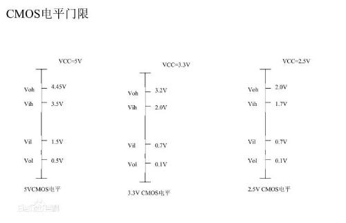
2. CMOS level interface
Many people know that under normal conditions, power consumption and noise immunity of CMOS is much better than that of TTL. But! What little is known is that at high switching frequency, CMOS series actually consume more power than TTL. As to why this is so, please ask theory of semiconductor physics.
Because CMOS operating voltage can be very low nowadays, and some FPGA cores operating voltage is even close to 1.5V, which makes noise margin between levels much smaller than TTL, exacerbating voltage fluctuations. resulting signal estimation error.
As we all know, input impedance of CMOS circuit is very large, so its coupling capacitance can be very small, and there is no need to use a large electrolytic capacitor. Because CMOS circuits typically have poor drive capability, TTL conversion must be performed before driving ESL circuits. In addition, when designing CMOS interface circuit, care must be taken to avoid large capacitive loads, otherwise rise time will be slower, and power dissipation of driver will also increase (because capacitive load does not consume power).
Comparison of TTL circuit and CMOS circuit
(1) TTL is a current control device and CMOS is a voltage control device.
(2) TTL circuit speed is fast, transmission delay time is short (5-10ns), but power consumption is large.
(3) The speed of CMOS circuit is low, transmission delay time is long (25-50ns), but power consumption is low.
3. ECL level interface
It's an old friend inside computer system! Since its speed "runs" fast enough, it can even reach hundreds of MHz! This is because BJT inside ECL is not in a saturation state when turned on, so turn-on and turn-off time of BJT can be reduced, and operating speed can be naturally increased.
But you have to pay for it! Fatal Injury: High Power Consumption! The electromagnetic interference problem that this causes is noteworthy, and anti-interference ability is not much better. If someone can compromise these two factors, then he (she) must get rich. It should also be noted that conventional ECL integrated circuit needs a negative power supply, that is, its output voltage is negative, and at this time a special level shifting circuit is required.
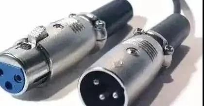
4. RS-232 level interface
In fact, no one who plays electronic technology knows about it (unless he or she is just an "amateur" in electronic technology). This is low speed serial interface standard. It should be noted that its level standard is a bit "anomalous": high level is -12V and the low level is +12V.
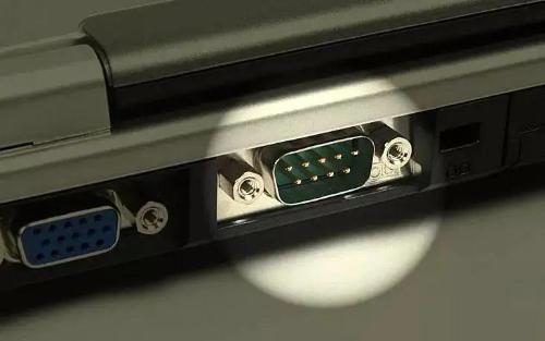
So, when we are trying to communicate with peripheral devices through a computer, MAX232 level conversion chip is, of course, indispensable. But we must be soberly aware of some of its shortcomings, such as relatively slow data transfer speed and short transmission range.
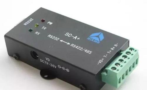
5. Differential balanced level interface
The relative output voltage (uA-uB) of pair of terminals A and B is used to represent signal. Typically, this differential signal passes through a complex noise environment during signal transmission, resulting in two lines. amount of noise generated on both, and energy of noise will be canceled on receiving side, so it can transmit longer distances and faster speeds.
The RS-485 interface commonly used in industry uses a differential transmission mode, which has good ability to withstand common mode noise.
6. Optical Isolation Interface
An optocoupler uses optical signals as a medium for communication and transmission of electrical signals. Its "advantage" is that it can provide galvanic isolation, so it has superior noise immunity. Under condition of high operating frequency of circuit, basically only high-speed photoelectric isolation interface circuit can meet needs of data transmission.
Sometimes, in order to achieve high voltage and high current control, we must design and use an optical isolation interface circuit to connect these low-level TTL or low current CMOS circuits as above, because input circuit of optical isolation interface and output circuit may withstand high voltages of several thousand volts, which is sufficient for general applications. In addition, input part and output part of optical isolation interface must use independent power supplies, otherwise electrical connection still exists, so it is not called isolation.
7. Coil connection interface
Its good isolation characteristics, but available signal bandwidth is limited. For example, transformer coupling, its power transfer efficiency is very high, and output power is basically close to its input power, so for a step-up transformer, it can have a higher output voltage, but it can only give a lower current.
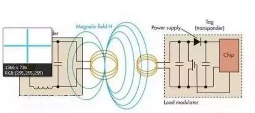
In addition, high-frequency and low-frequency characteristics of transformer are not optimistic, but its biggest feature is that it can realize impedance conversion. With proper matching, load can receive sufficient power. Very popular in circuit engineering. .
Related
- must read! Electronics Engineers Must Master 7 Common Interfaces in Circuits
- Common Mistakes of Electronics Engineers
- The best switching circuit design process for power supplies is a must for engineers!
- (Detailed long text) 7 ways to use diodes that engineers need to master
- Commonly Used Diode Circuits Essential for Engineers
- Inventory of 27 functions of capacitors in circuits
- List of 5 Most Practical Network Analysis Techniques! must watch
- You must learn drawing techniques and skills of 18 special circuit board routes.
- Experience in recognition of circuit diagrams of electronic circuits and method of circuit analysis
- Three common grounding methods in circuit design
Hot Posts
 How to distinguish induction from leakage, we will teach you three tricks! Ordinary people can also learn super practical
- What is drowning in gold? Why Shen Jin?
- This is a metaphor for EMI/EMS/EMC that can be understood at a glance.
- How many types of pads have you seen in PCB design?
- Summary of Common PCB Repair Techniques
- What is three anti-paint? How to use it correctly?
- Knowing these rules, you will not get confused looking at circuit diagram.
- How to make anti-interference PCB design?
- Can diodes do this?