Location:Home Page > Archive Archive
How to intelligently prevent positive and negative poles of a power supply from being reversed?
2023-03-18【Archive】
Many hardware engineering projects are done on perforated boards, but there is a phenomenon where positive and negative poles of a power supply are accidentally reversed, causing many electronic components to burn out or even destroy entire board. Another piece of welding, don't know how to solve it?
First, sloppiness is inevitable. Although it's only to distinguish between positive and negative wires, one red and one black, we can connect it once and we won't go wrong; we can't go wrong if we connect wires 10 times, but 1000 times? What about 10,000? At moment it is difficult to say. Due to our carelessness, some electronic components and microcircuits burned out. The main reason is that components failed due to excessive current, so measures must be taken to prevent reverse switching.
The following methods are commonly used:
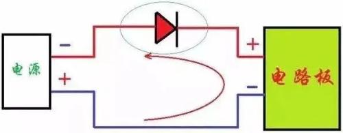
01 Diode series reverse connection protection circuit
A forward diode is connected in series with positive power supply input terminal to take full advantage of forward conduction and reverse cutoff characteristics of diode. Normally diode conducts and board works.
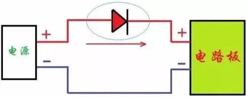
When power supply is reversed, diode is turned off, power supply cannot form a loop, and circuit board does not work, which can effectively prevent reverse power problem.
02 Bridge rectifier reverse connection protection circuit
Use a rectifier bridge to change input power to non-polarity, whether power is connected positively or vice versa, PCB will work normally.
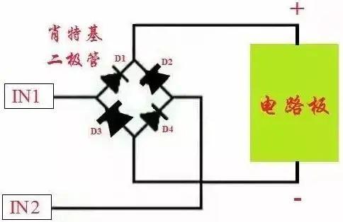
The above example uses diodes for anti-reverse processing. If silicon diodes are used, voltage drop will be about 0.6~0.8V, and germanium diodes will also have a voltage drop of about 0.2~0.4V. reverse processing, voltage drop of a MOS lamp is very small, down to a few milliohms, and voltage drop is almost negligible.
03 MOS lamp reverse protection circuit
Due to improvement of technology and its own nature, internal conduction resistance of MOS tube is small, many of which are in milliohm level or even less, so that loss caused by voltage drop and power consumption of circuit is particularly small, and may even be negligible, so MOS tube is recommended to protect circuit.
1) NMOS protection
As shown in figure below: At moment of power-on, parasitic diode of MOS lamp turns on, and system forms a loop. The source potential S is about 0.6V, and gate potential G is Vbat, and turn-on voltage of MOS lamp is extremely large : Ugs = Vbat - Vs, gate is high, ds NMOS is on, parasitic diode is shorted, and system loops through ds NMOS.
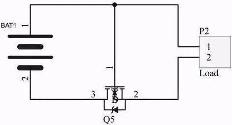
If power supply is reversed, conduction voltage of NMOS is 0, NMOS turns off, parasitic diode reverses, and circuit turns off, thus forming a protection.
2) PMOS Protection
As shown in figure below: at moment of power-on, parasitic diode of MOS lamp turns on, and system forms a loop. The source potential S is about Vbat-0.6V, and gate potential G is 0, and turn-on voltage of MOS lamp is extreme : Ugs = 0 - (Vbat-0.6), gate low, ds PMOS is on, parasitic diode is short-circuited, and system forms a loop through ds PMOS.
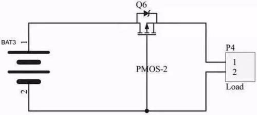
If power supply is reversed, conduction voltage of NMOS is greater than 0, PMOS turns off, parasitic diode reverses, and circuit turns off, thereby forming a protection.
Note. The NMOS transistor is connected to negative pole, PMOS transistor ds is connected to positive pole, and direction of parasitic diode corresponds to direction of current when connected correctly.
Connection of D pole and S pole of MOS tube: When using N-channel MOS tube, current usually enters from D pole and flows out of S pole, and PMOS is S and D out input that is used in this circuit. When opposite is true, voltage condition for conduction of MOSFET is satisfied by conduction of parasitic diode.
The MOS lamp will be fully on as long as appropriate voltage is established between G and S poles. After switching on, it is, as it were, closed by a switch between D and S, and current has same resistance from D to S or from S to D.
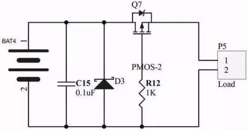
In practice, a resistor is usually connected in series with G pole. A zener diode can also be added to prevent MOS lamp from failing. A capacitor connected in parallel with voltage divider resistor provides a soft start. At moment when current begins to flow, capacitor is charged, and voltage of electrode G is gradually established.
PMOS, compared with NOMS, requires Vgs to be larger than threshold voltage. Because its turn-on voltage can be 0, voltage difference between DS is small, which is more advantageous than NMOS.
04 Fuse
For many common electronic products, you may see a fuse added to power supply after disassembly. Repair and replacement is thus difficult.
Related
- How to intelligently prevent positive and negative poles of a power supply from being reversed?
- When designing a power supply, how to consider choice of topology?
- Four ways to reduce the output "ripple and noise" of a switching power supply
- What is power supply ripple, how to measure their magnitude and how to suppress?
- Analysis of various losses inside a switching power supply from 4 aspects
- How does internal resistance affect a power supply?
- Analysis of damping RC circuit of a switching power supply "haberdashery"
- Detailed analysis of the "various protection schemes" of a switching power supply
- Analysis and comparison of 6 most commonly used DC power supply circuits
- Finally, it becomes clear that process of obtaining switching losses of a MOSFET in a switching power supply
Hot Posts
 How to distinguish induction from leakage, we will teach you three tricks! Ordinary people can also learn super practical
- What is drowning in gold? Why Shen Jin?
- This is a metaphor for EMI/EMS/EMC that can be understood at a glance.
- How many types of pads have you seen in PCB design?
- Summary of Common PCB Repair Techniques
- What is three anti-paint? How to use it correctly?
- Knowing these rules, you will not get confused looking at circuit diagram.
- How to make anti-interference PCB design?
- Can diodes do this?