Location:Home Page > Archive Archive
Power port lightning protection circuit
2023-03-18【Archive】
There are many factors to consider when designing a power port lightning protection circuit, including following:
1. The design of lightning protection circuit must meet requirements of given protection level, and level of residual voltage of lightning protection circuit must be able to protect subsequent circuit from damage.
2. When encountering a lightning transient overvoltage, protective device must have a sufficiently fast response time, that is, it can operate as quickly as possible to limit voltage and discharge bypass.
3. A lightning protection circuit has been added to feeder line, which should not affect normal equipment feeder. For example, when using a lightning protection circuit of a serial power supply, lightning protection circuit must be able to carry current at full load of equipment and have a certain margin.
4. The protection circuit should not operate at highest operating voltage of system. Typically, in an AC circuit, operating voltage of protective circuit is 2.2 to 2.5 times effective value of operating voltage of AC, and in DC circuit, operating voltage of protective circuit is 1.8 to 2 times rated operating voltage of DC. .
5.A lightning protection scheme has been added to feeder line, which should not carry hidden dangers for safe operation of equipment. For example, safety hazards such as fire and other safety hazards in lightning protection circuits due to improper circuit design should be avoided.
6. If there are multi-level lightning protection circuits on entire supply path, it should be noted that there is a good coordination connection between lightning protection circuits at all levels. The circuit is in good condition.
7. The lightning protection circuit must have functions of alarm, remote signaling, thermal capacity and overcurrent protection, and be replaceable.
The following are guidelines for designing lightning protection circuits for the AC power port and DC power port, respectively.
1. AC power port lightning protection circuit
1. AC power port lightning protection circuit
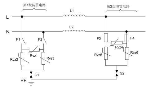
The picture above shows a two-stage AC power port protection scheme:
a, G1 and G2 are gas discharge tubes
2. Rvz1~Rvz6 - varistors
3, F1 and F2 are air switches
4, F3 and F4 - insurance
5. L1 and L2 are decoupling inductors.
The principle of schema is briefly described as follows:
The first level lightning protection circuit is a circuit with common mode and differential protection, and differential protection uses a varistor. Common mode protection uses a piezoresistor in series with gas discharge tube. The current capacity of first level lightning protection circuit is relatively high, usually tens of kA (8/20 µs). The first level lightning protection circuit should use an air circuit breaker as a short circuit and overcurrent protection device.
The form of second level lightning protection scheme is same as that of first level scheme. Reasonable design of inductance value between first level circuit and second level circuit can make most of lightning current discharge through first level lightning protection circuit. The second level circuit only discharges a small part of lightning current, so that output residual voltage of lightning arrester can be further reduced by second level circuit level to achieve purpose of protecting downstream equipment. The second level lightning protection circuit must use insurance as a protective device.
The choice of flow of each protective device in protection circuit must meet requirements of calculated index and have a certain margin; voltage value of differential varistor varistor can be selected according to method given in varistor chapter; In common mode protection circuit connected in series with discharge tube, values of varistor and discharge tube can still be selected according to calculation methods given in respective chapters when varistor and discharge tube of pipe are connected separately in line.
Second, modification of AC power port lightning protection circuit
1. Modified scheme 1
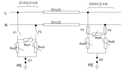
AC Power Port 1 Upgrade Diagram
In modified circuit 1, inductance in original circuit is replaced by a feeder of a certain length. The inductance of a feeder of a given length is basically same as inductance in original circuit. The advantage of replacing inductance with feeder line is that when operating current of equipment is very large, reasonable selection of diameter of feeder wire can meet power supply requirements of equipment and solve problem of air-core inductors. when supply current of equipment is large Problems that are too cumbersome to implement in circuit. The first-level protection circuit and second-level protection circuit can be implemented in two different devices, for example: first-level protection circuit is implemented as an independent lightning protection box, and second-level protection circuit is built into communication equipment.
Since inductance is removed, modified circuit 1 can be considered as two lightning protection circuits in parallel. When performing a two-level lightning protection scheme in form of two separate lightning protection devices, attention should be paid to installation of lightning protection devices.
2. Modified scheme 2
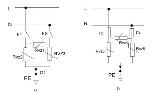 AC Power Port Modification Diagram 2
Scheme option 2 is a simplified design of AC lightning protection circuit: only first level lightning protection circuit or second level lightning protection circuit in lightning protection circuit is retained, and rest of calculated moments are same as those of lightning protection circuit. AC power port lightning protection circuit.
Circuit a is used when downstream circuit is highly resistant to overvoltage and circuit b is used when there is an external primary protection, which is usually placed inside power module. Deformed Circuit 2 reduces complexity of circuit, and since inductance is removed, there is no need to consider requirement to provide normal operating current through device and solution is easier to implement. Since there is no inductance in circuit, it changes from a series lightning protection circuit to a parallel lightning protection circuit. When this circuit becomes an independent lightning rod, attention should be paid to installation of lightning rod.
3. DC power port lightning protection circuit design
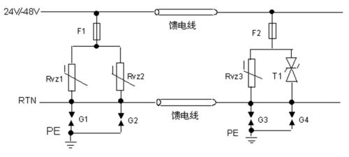
1. DC power port lightning protection circuit
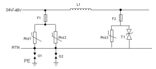
The image above shows a circuit with two-level differential protection in series, which can provide a nominal discharge current of 5 kA. The principle of operation of circuit is briefly described as follows:
The first stage uses differential protection of two parallel varistors and common mode protection of two gas discharge tubes in parallel (Note: purpose of choosing two devices in parallel is to reduce residual voltage and increase bandwidth. If one device meets requirements, then only one device can be used) , which can reach design discharge current rating of 5kA, and second level is protected by varistors and TVS tubes to reduce residual voltage to a level that subsequent circuit can withstand, Among them, for TVS T1 tube, it is recommended to use a bidirectional TVS tube, which can prevent reverse connection, and a unidirectional TVS tube can also be used, but it has disadvantage of not preventing reverse connection. Common mode protection uses a level 1 protection circuit consisting of two gas discharge tubes connected in parallel. The advantage of this circuit is that it has a lower output residual voltage, which is suitable for situation where overvoltage protection level of downstream circuit is very low. The choice of flow rate, varistor voltage, reverse breakdown voltage and inductance value of each protection element in a lightning protection circuit can be made by referring to methods given in respective chapters. The two-level lightning protection scheme must use insurance as a protective device.
The application case of this protection circuit is that ability of subsequent surge protection circuit is weak, and first level lightning protection circuit is not enough to protect subsequent equipment, and residual voltage needs to be further reduced by second level lightning protection circuit.
Fourth, modification of DC power port lightning protection circuit
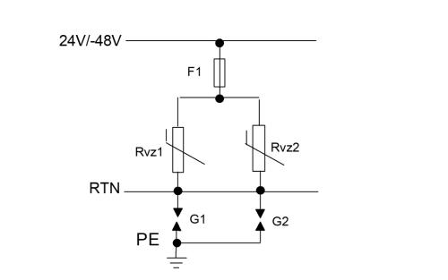
1. Modified scheme 1
DC Power Port 1 Upgrade Diagram
In modified circuit 1, inductance in lightning protection circuit of DC power port in fig. 6-4 is replaced by a feeder of a certain length. The inductance of a feeder of a given length is basically same as inductance in original circuit. The advantage of replacing inductance with feeder line is: when operating current of equipment is very large, reasonable selection of wire diameter of feeder line can meet power supply requirements of equipment, and overcome volume of air-core inductor when equipment supply current is large Problems that are too large to be implemented in chains. The first-level protection circuit and second-level protection circuit can be placed in two different devices, for example: first-level protection circuit is built into a high-resistance DC cabinet, and second-level lightning protection circuit is built into communication equipment.
Since inductance is removed, modified circuit 1 can be considered as two lightning protection circuits in parallel. When performing a two-level lightning protection scheme in form of two separate lightning protection devices, attention should be paid to installation of lightning protection devices.
2. Modified scheme 2
Modification diagram for DC power port 2
Circuit Option 2 is a simplified design of DC power port lightning protection circuit: first level lightning protection circuit in lightning protection circuit is retained (Note: The purpose of connecting two devices in parallel here is to reduce residual voltage and increase throughput. In case of using one device, to meet requirements, only one device can be used), and inductance and second level lightning protection circuit are removed. Other design features are same as DC power port lightning protection circuit.
Application of modified circuit 2 is used when subsequent circuit has a high surge capacity. This solution can reduce circuit complexity. At same time, since inductance is removed, there is no need to take into account need to meet requirements of normal operating current passing through device, and solution is easier to implement. Since modified circuit 2 had inductance removed, it was changed from a series lightning protection circuit to a parallel lightning protection circuit. When this circuit becomes an independent lightning rod, attention should be paid to installation of lightning rod.
Related
- Power port lightning protection circuit
- Circuit Analysis of 6 Examples Explaining Lightning Surge Protection in Detail
- What is difference between surge device, lightning arrester, leakage protection, circuit breaker and circuit breaker? Come and get knowledge
- Analysis of power circuit of a classic single-chip microcomputer
- Analysis of damping RC circuit of a switching power supply "haberdashery"
- Detailed analysis of the "various protection schemes" of a switching power supply
- The best switching circuit design process for power supplies is a must for engineers!
- Experience in recognition of circuit diagrams of electronic circuits and method of circuit analysis
- Optocoupler and application circuit
- Industrial Computer Circuit Design
Hot Posts
 How to distinguish induction from leakage, we will teach you three tricks! Ordinary people can also learn super practical
- What is drowning in gold? Why Shen Jin?
- This is a metaphor for EMI/EMS/EMC that can be understood at a glance.
- How many types of pads have you seen in PCB design?
- Summary of Common PCB Repair Techniques
- What is three anti-paint? How to use it correctly?
- Knowing these rules, you will not get confused looking at circuit diagram.
- How to make anti-interference PCB design?
- Can diodes do this?