Location:Home Page > Archive Archive
Popularizing common sense inductors
2023-04-06【Archive】
An inductor is also one of widely used components in household appliances, appliances and other electronic products. It is an electronic component that works on principle of electromagnetic induction. Its electrical characteristics are opposite of those of capacitors, "passing low frequencies and blocking high frequencies". When a high frequency signal passes through inductor, it will meet a lot of resistance and it will be difficult to pass through it, while resistance to passage of a low frequency signal is relatively small, that is, a low frequency signal can pass through it more easily. The resistance of inductor coil to direct current is practically zero.
In electronic circuits, an inductor is mainly used to isolate and filter AC signals, or to form a resonant circuit with capacitors and resistors.
In circuit diagram, inductor is marked with letter L.
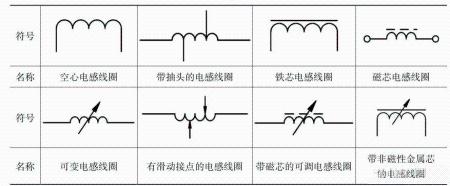
Classification of inductors
There are many types of inductors, and classification methods vary.
Classified according to wire core, it can be divided into air core inductor coil, magnetic core inductor coil, iron core inductor coil and copper core inductor coil.
Classified according to shape of installation, they can be divided into vertical and horizontal inductors.
Classified by operating frequency, they can be divided into high frequency inductors, medium frequency inductors and low frequency inductors.
Classified by purpose, it can be divided into power filter coils, high-pass filter coils, high-frequency choke coils, low-frequency choke coils, line deflection coils, field deflection coils, linear oscillation coils, linear correction coils, local oscillation coils. coils, high frequency oscillatory coils.
Depending on whether inductance is adjustable, it can be divided into fixed inductance coils, variable inductance coils, and coils with fine inductance adjustment.
According to winding method and structure, inductors can be divided into single-layer, multi-layer, honeycomb, frame and non-frame inductors.
The way inductor models are named
The inductor model mainly consists of four parts: main name, specification, type and difference code:
First part: main name, letter L for coil and ZL for choke coil;
Second part: functions using G to represent high frequencies;
Third part: enter, use X to indicate small size;
Fourth part: recognize codes, use letters A, B, C, etc.
For example, LGX means a small plastic high frequency inductor.
Basic characteristic parameters of an inductor
1. Inductance
Inductance refers to amount of intrinsic inductance that occurs when an inductor conducts current.
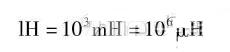
The unit of inductance is Henry, denoted by letter H. Commonly used units are millihenry (mH), microhenry (µH). Their conversion ratio:
2. Dignity
The ratio of stored energy to consumed energy in an inductor is called quality factor, also known as Q value, and its definition is:
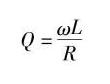
In formula, w is corner frequency T, L is inductance of coil, and R is loss impedance of coil.
3. Rated current
The rated current of an inductor coil refers to maximum current flowing through an inductor coil during normal operation. The rated current is an important parameter for high frequency, low frequency choke coils and high power resonant coils.
4. Distributed Capacity
Distributed capacitance refers to capacitance formed between turns of coil, that is, capacitance formed by air, insulating layer of wire and frame. The sum of these capacitances and resistance of inductor itself form a resonant circuit that creates a resonance of a certain speed, reduces stability of inductance of inductor and reduces value of Q. Usually, distributed capacitance must be reduced. In order to reduce distributed capacitance of an inductor, various control methods are commonly used, such as interwinding winding method and honeycomb winding method.
Related
- Popularizing common sense inductors
- In PCB industry, we all need to know these 5 important common sense rules.
- What is difference between 0 ohm resistors, inductors and magnetic balls for single point grounding?
- What is difference between 0 ohm resistors, inductors and magnetic balls? After reading this I finally got the answer
- Common Mistakes of Electronics Engineers
- 50 Common Hardware Design Patterns
- Summary of Common PCB Repair Techniques
- Hardware Collection: 50 Common Circuit Diagrams
- Three common grounding methods in circuit design
- Common USB Interface Circuit Design Problems and Solutions
Hot Posts
 How to distinguish induction from leakage, we will teach you three tricks! Ordinary people can also learn super practical
- What is drowning in gold? Why Shen Jin?
- This is a metaphor for EMI/EMS/EMC that can be understood at a glance.
- How many types of pads have you seen in PCB design?
- Summary of Common PCB Repair Techniques
- What is three anti-paint? How to use it correctly?
- Knowing these rules, you will not get confused looking at circuit diagram.
- How to make anti-interference PCB design?
- Can diodes do this?