Location:Home Page > Archive Archive
Is applying an LC resonant circuit too complicated? Actually this step is very important.
2023-05-05【Archive】
According to different methods of connecting inductor L and capacitor C, there are two main LC resonant circuits in circuit: parallel LC resonant circuit and series LC resonant circuit.
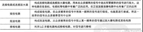
In amplifier circuits and other forms of signal processing circuits, parallel LC resonant circuits and series LC resonant circuits are widely used. The following figure describes application of LC resonant circuit:
The parallel and series LC resonant circuits have many variations in application, which is a difficult point when analyzing circuit.
01
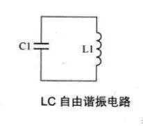
LC free resonant circuit
The figure below shows a free LC resonant circuit. L1 in circuit is an inductor, C1 is a capacitor, and L1 and C1 form a parallel circuit.
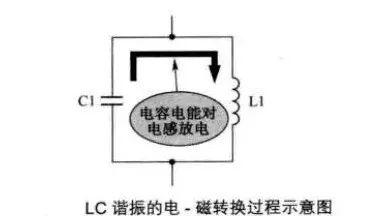
As shown in figure below, main resonant process of LC resonant circuit: Suppose there is electrical energy in capacitor C1 at beginning, then electrical energy of C1 is discharged into L1, this process is that electrical energy of energy in C1 is converted into magnetic energy in coil L1. In this case, when capacitor C1 is discharged, all energy is stored in coil L1 in form of magnetic energy.
As shown in figure below, after discharge of C1 is completed, magnetic energy in coil L1 charges C1 as a current generated by self-induced electromotive force at both ends of coil. This charging process is that magnetic energy in coil L1 is converted into electrical energy in capacitor C1 during operation.
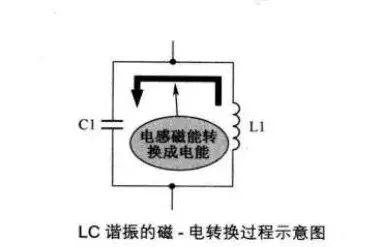
After capacitor C1 is fully charged, voltage across capacitor discharges coil again, starting a new oscillation cycle and energy conversion process.
02
LC parallel resonant circuit
The figure below shows an LC parallel resonant circuit. L1 and C1 in circuit constitute a parallel LC resonant circuit. R1 is DC resistance of coil L1. Is is an AC signal source, which is a DC source. A so-called constant current source is a power source whose output current does not change when load changes. For convenience of discussing LC-parallel circuit, coil resistance R1 can be neglected, and a simplified circuit is shown in the figure below.
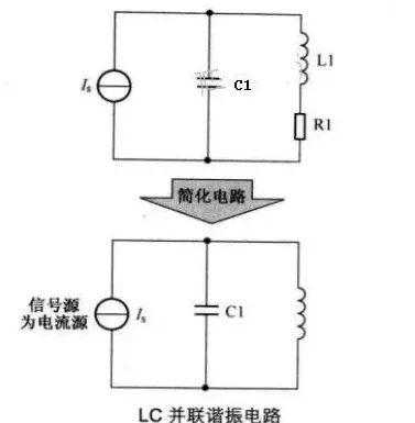
The resistance of an LC-parallel resonant circuit can be equivalent to a resistor. This is a special resistor whose resistance value changes depending on frequency. This equivalence can make it easier to understand how circuit works.
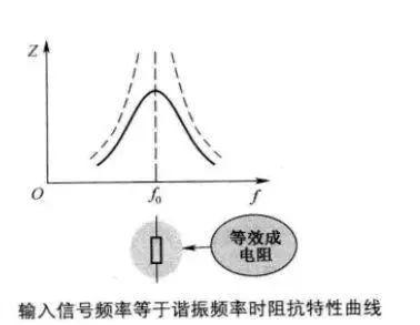
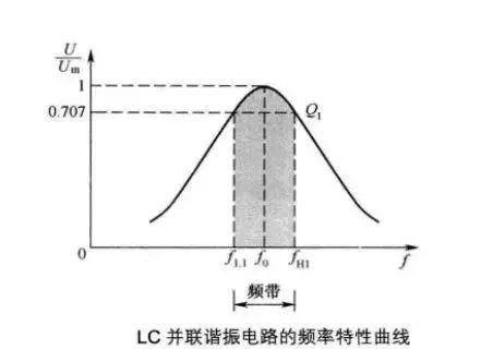
An important characteristic of a parallel LC circuit: The impedance of circuit reaches its maximum when parallel resonance occurs.
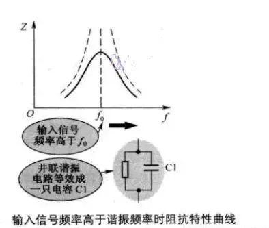
When frequency of input signal is higher than resonant frequency, LC parallel resonant circuit is equivalent to a capacitor.
① Impedance characteristic curve when input signal frequency is equal to resonant frequency:
② Impedance characteristic curve when input frequency is higher than resonant frequency:
③ When input signal frequency is lower than resonant frequency, impedance characteristic curve:
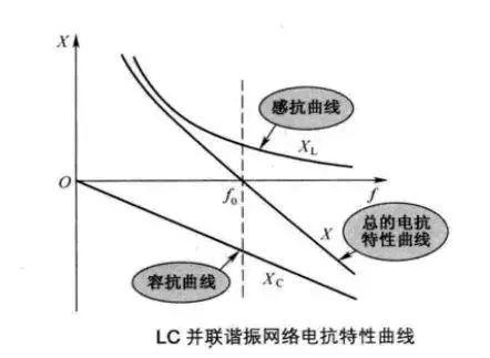
④ LC parallel resonant network reactance curve:
⑤ Frequency response curve of LC-parallel resonant circuit:
03
LC series resonant circuit
LC series resonant circuit is another kind of resonant circuit in LC resonant circuit.
The figure below shows LC series resonant circuit. R1 in circuit is DC resistance of L1 coil as well as damping circuit of this LC series resonant circuit. L1 and C1 are connected in series and then connected in parallel to a signal source where the signal source is a DC voltage source.
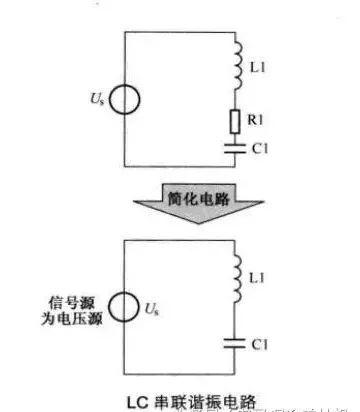
In LC series resonant circuit, smaller value of resistor R1, smaller power consumption of resonant signal, better quality of resonant circuit, and higher quality factor of circuit. When inductance L1 in circuit is larger, accumulated magnetic energy is also larger, and quality of resonant circuit is better, when loss in circuit is constant, and quality factor of circuit is also higher.
In circuit, there is no mutual conversion of energy between signal source and LC resonant circuit sequence, but there is a mutual conversion between electrical energy and magnetic energy between capacitor C1 and inductor L1, and additional input signal is only additional due to consumption of electrical energy resistor R1 and signal energy loss.
Related
- Is applying an LC resonant circuit too complicated? Actually this step is very important.
- Anti-reverse connection is very important, make good use of these 4 commonly used circuits
- Is printed circuit board covered with copper very “up to mark”? One article to help you get practical guidelines and norms
- Does circuit diagram actually contain that much truth?
- TVS choice, this experience is comfortable
- What is difference between surge device, lightning arrester, leakage protection, circuit breaker and circuit breaker? Come and get knowledge
- Principal analysis of BUCK / BOOST circuit, a summary is also in place
- Why is shielded wire so important? But remember about one-way grounding!
- What is a delay scheme? Explanation of 6 Kinds of Delay Circuit Principles
- Surprisingly, this is most prone to PCB failure?
Hot Posts
 How to distinguish induction from leakage, we will teach you three tricks! Ordinary people can also learn super practical
- What is drowning in gold? Why Shen Jin?
- This is a metaphor for EMI/EMS/EMC that can be understood at a glance.
- How many types of pads have you seen in PCB design?
- Summary of Common PCB Repair Techniques
- What is three anti-paint? How to use it correctly?
- Knowing these rules, you will not get confused looking at circuit diagram.
- How to make anti-interference PCB design?
- Can diodes do this?