Location:Home Page > Archive Archive
The use of 0 ohm resistance is finally summarized this time.
2023-08-17【Archive】
Null resistance, also known as jumper resistance, is a special purpose resistor. Zero resistance is not really zero resistance (that's what superconductors do). Because of resistance, it is also same as conventional chip resistors. have same error rate.
The following are examples of using resistors with zero resistance:
01 There is no function in schematic, only on PCB for ease of debugging or compatible design and other reasons.
02Can be used as a jumper. If a line is not used, just don't insert a resistor (doesn't affect appearance)
03 If matching network parameters are not clear, replace them with zero resistance. During actual debugging, determine parameters and replace them with components with specific values.
04 If you want to measure current draw of a certain part of circuit, you can remove 0 ohm resistor and connect an ammeter, which is handy for measuring current draw.
05 When connecting, if you can't pass it, you can also add a zero resistance resistor
06 Acts like an inductor or capacitor for high frequency signals. This is due to characteristics of external circuit, mainly to solve EMC problem. For example, ground and ground, between power supply and IC pin.
07 Single point grounding (meaning that safety ground, service ground, and DC ground are separated from each other on equipment and each becomes an independent system) < /p>
08 Combine Action
09 Single-point grounding of quasi-ground and digital ground
While this is ground wire (GND), eventually it needs to be connected together and then to ground. If they are not connected together, they will "float" and a voltage difference will occur that easily builds up charges and causes static electricity. Ground is referenced to 0 potential and all voltages are obtained with respect to ground. Grounding standards must be consistent, so various grounds must be shorted together. It is believed that Earth absorbs all charges, always remains stable and is earth's final reference point. While some boards are not connected to ground, power plant is connected to ground and power on board will eventually return to power plant and be grounded. If analog ground and digital ground are connected directly over a large area, it will cause mutual interference. Not short-circuiting is impractical, and reason is as follows. There are four ways to solve this problem:
(1) connect with magnetic beads;
(2) connect condensator;
(3) connect with inductance;
(4) Connect a resistor with zero resistance.
The magnetic bead equivalent circuit is equivalent to a bandstop wave limiter, which can only significantly suppress noise at a certain frequency point, when using it, it is necessary to estimate frequency of noise point in advance to select appropriate model. In situations where frequency is uncertain or unpredictable, magnetic beads are not suitable. The capacitor directly blocks traffic, causing a floating ground. The inductor has a large volume, many parasitic parameters and is unstable. Zero resistance resistance is equivalent to a very narrow current path, which can effectively limit loop current and suppress noise. Resistors have a damping effect over all frequency ranges (zero ohm resistors also have an impedance) that is stronger than ferrite beads.
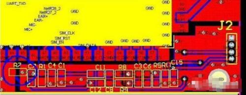
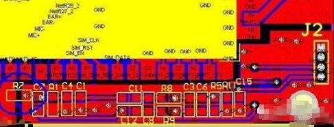
The next two diagrams show schematic, but part numbers are different. R7 (R33) is the single point end of analog and digital ground.
10 For current loops when crossing
When electrical ground plane is separated, shortest signal return path is interrupted. At this time, signal loop must be bypassed, forming a large area of the loop, and influence of electric field and magnetic field becomes stronger, and it is easy to interfere/tamper. Connecting a zero ohm resistor across baffle can provide a shorter return path and reduce interference.
11 Configuration schema
In general, there should be no jumpers or DIP switches on product. Sometimes users will fiddle with settings, which can easily cause misunderstandings. In order to reduce maintenance costs, zero resistance resistors are used instead of jumpers, which are soldered to board. The loose jumper is equivalent to an antenna at high frequencies, and effect of using chip resistors is good.
12 Other uses
Crossover during posting;
For debugging/testing;
Temporarily replace other patch devices;
As a temperature compensation device
Most often this is due to need to counteract electromagnetic compatibility. Also, zero ohm resistors have less parasitic inductance than vias, and vias also affect ground layer (due to need for digging holes). Also, different sizes of zero resistance resistors allow different currents to pass, typically 1A for 0603 and 2A for 0805, so different sizes will be used for different currents. magnetic balls and inductors Size also packed, so 0603, 0805 and other sizes are available.
Related
- The use of 0 ohm resistance is finally summarized this time.
- What is difference between 0 ohm resistors, inductors and magnetic balls? After reading this I finally got the answer
- It suddenly dawned on me that a 0 ohm resistor can still be used like this
- What is difference between 0 ohm resistors, inductors and magnetic balls for single point grounding?
- Engineer Daniel tells you: The "Y Capacitor" of a switching power supply is calculated in this way.
- The SD card is broken, can it be fixed this way?
- The essence of PID control algorithm is here
- Anti-reverse connection is very important, make good use of these 4 commonly used circuits
- How to independently check malfunction of parallel resistance circuit? Chart details
- What is a magnetic sensor? The most common types of magnetic sensors and their applications
Hot Posts
 How to distinguish induction from leakage, we will teach you three tricks! Ordinary people can also learn super practical
- What is drowning in gold? Why Shen Jin?
- This is a metaphor for EMI/EMS/EMC that can be understood at a glance.
- How many types of pads have you seen in PCB design?
- Summary of Common PCB Repair Techniques
- What is three anti-paint? How to use it correctly?
- Knowing these rules, you will not get confused looking at circuit diagram.
- How to make anti-interference PCB design?
- Can diodes do this?