Location:Home Page > Archive Archive
Share 8 circuit diagrams of 100W power amplifier
2023-10-05【Archive】
01
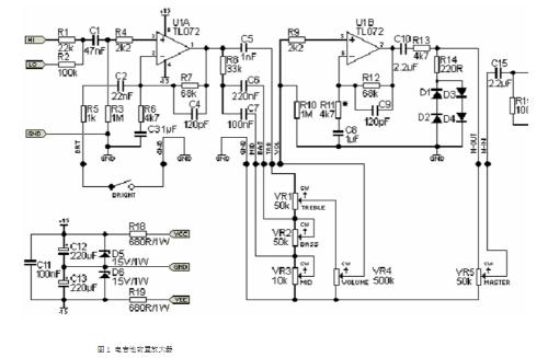
100W class D power amplifier circuit
Introduce a 100W class D power amplifier circuit made up of conventional components for reference of music lovers. The circuit is shown in Figure 1.
Key points when choosing components:
Ic1 uses CD4013 double D flip-flop. IC2 uses TC4426 high-speed MOSFET drive circuit, IC can work stably in supply voltage range of 4.5-18V, its drive output current reaches 1.5A, and output impedance is only 7Ω (internal circuit is shown in Fig. 2) , so it is an ideal device for driving MOSFET power amplifier tubes in digital power amplifiers. The output lamp is an IRFP140 MOSFET (100V, 30A, 150W). D1 and D2 use MBR150 fast Schottky diodes. If MBR150 is not available, other diodes of same type can be used instead. The T1 uses 1mm diameter high tensile enamelled wire on a 25mm diameter 3C85 core and winds 8 turns. The T2 primary winding uses 1mm diameter high strength enameled wire to wind 6 turns on one core, and T2 secondary winding uses 0.8mm diameter high strength enameled wire to wind 21 turns on same core. The L1 uses a high strength 0.8mm diameter enameled wire to tightly wind 64 turns on a T-157-2 ferrite core. The L2 uses a high strength 0.8mm diameter enameled wire to tightly wind 64 turns on a T-130-2 ferrite core. If power amplifier has noise during operation, a 47nF capacitor can be added to voltage input terminal (near pin) of CD4013 and TC4426. Resistors - metallized resistors with five-color rings, power of 2.2 Ohm resistor of control pole of MOSFET output tube is 2 W, three 470 nF capacitors are WIMA capacitors, rest are ordinary capacitors. The component parameters are shown in Figure 1.
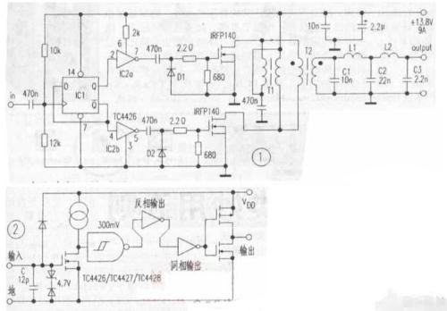
The power supply voltage of this machine is only 13.8V, so output current of power supply is relatively high, and current must be greater than 9A to ensure that power amplifier can work normally in high power mode. . If conditions permit, power supply can be converted into a switching power supply with an output voltage of 14V.
When output impedance is within 4-16 ohms, power amplifier can work normally and efficiency is above 76%. Thanks to presence of T2 output transformer, output sound is very similar to tube amplifiers, audio lovers can try.
02
High quality power amplifier circuit
The fully symmetrical complementary circuit structure is adopted, and all components are strictly coupled for use, so that constant current of power amplifier is reliably guaranteed. The input stage is a cascode circuit with excellent linearity, followed by a compound common-emitter circuit to form main amplifier stage, which is very useful for expanding dynamics and improving resolution. The output power is a three-stage Darlington circuit, which, due to its extremely high current gain, can easily drive Dashi speakers. Each level of this machine's circuitry has a specific level of feedback to minimize open-loop distortion as much as possible, and overall feedback is only controlled at about 16 dB.
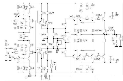
Debugging is also very easy. Adjust VR1 so that voltage drop across 2.4kΩ first stage load resistance is 6V, adjust VR2 to make midpoint equal to 0V, and adjust VR3 so that each lamp's quiescent current is 100mA at end stage. *A1209/C2911 calculation tube must be installed with heatsink. In this block, an experiment was carried out to tune general feedback circuit: feedback point of left channel circuit was moved from point A to form a feedback power amplifier without a large circuit, and feedback point of right channel was extended. from point B, which is so-called loop. One-way feedback power amplifier, turn it on for comparison and listening, you can hear that sound quality of left channel is clearly better than that of right channel, sound of left channel is extremely transparent and pure, and transient response very good, while sound of right channel is a little muddy, analysis power is not high. It is believed that this experiment has a certain meaning for many enthusiasts.
03
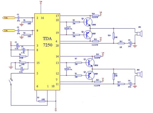
Amplifier circuit on TDA7250
04
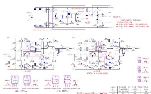
Discrete power amplifier circuit
05
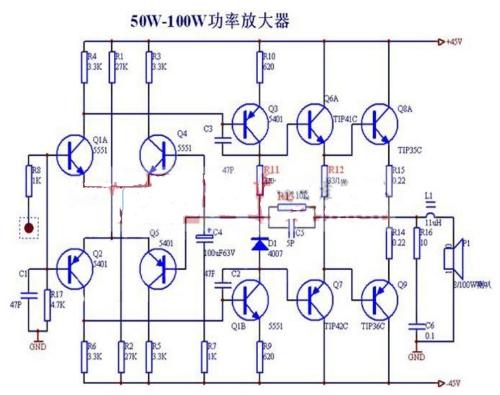
50-100W Power Amplifier Circuit
Simple 50-100W voltage audio power amplifier, this circuit is related to voltage power amplifier, biggest advantage is that it is very easy to make! As long as you follow method given above in circuit diagram, you can only succeed once. The debug method is also very simple. The main adjustment components: R11, R12, R13 to adjust quiescent current R11 and R12.
06
Additional power amplifier circuit
This circuit has a symmetrical structure, and there is no complex debugging process in it, except that transistors must match increase. This circuit requires a decoupling capacitor at output of sound source, otherwise a short circuit may occur. The improvement method is very simple, just add an isolating capacitor at input stage (the isolating capacitor should use nature of capacitor to "pass AC and block DC", and it is used where there should be DC). insulated), electrolytic capacitor 10uF 50V. Applicable. A single emitter follower has a small output impedance and a large load capacity, but its quiescent current is large, so power conversion efficiency is low. To improve efficiency, operating quiescent point of transistor is set in cutoff region. The disadvantage at present is that during one period of input signal, output voltage has only a half-cycle waveform, i.e. severe cutoff distortion. To make waveform complete, NPN tube consists of an emitter follower with opposite polarity. Thus, a complementary symmetrical chain is formed. The capacitors in the circuit require a withstand voltage of at least 50V.
07
PLPC1342V power amplifier circuit
Power amplifier circuit composed of pLPC1342V and NE (the second company's well-known fever tube pairs 2SC2987A and 2SA1227A, maximum output power can reach 120W, and cutoff frequency can reach 500MHz. Its collector output current can reach 12A.
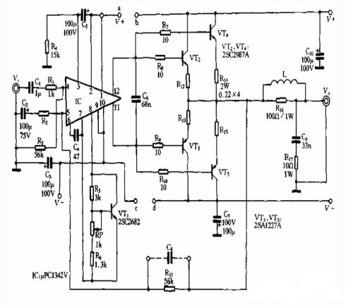
The output stage of this circuit uses a two-pipe parallel output, purpose of which is to increase output power. The operating voltage of circuit is ±45V. Increasing operating voltage can increase output power, but lamp consumption and heat dissipation of power amplifier lamp also increase, so power supply voltage must be reduced as much as possible to meet requirements. output power requirements. For a power amplifier circuit consisting of 2SC2987A/2SA1227A, final stage power must not exceed ±45 V. A regulated power supply can also be used. When front and back stages share a common set of power supplies, you can connect a and b, c and d in figure together.
08
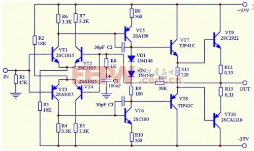
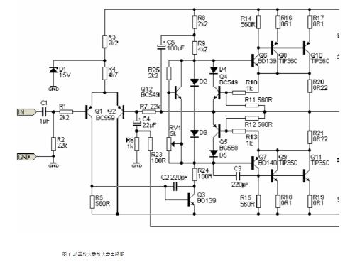
100 W power amplifier circuit
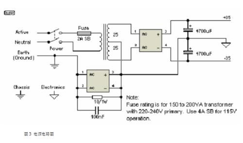
The bias current is adjustable, static current should be about 25mA, rated output power is 100W, 4Ω, power supply is 35V positive and negative balanced power supply
Related
- Share 8 circuit diagrams of 100W power amplifier
- Experience in recognition of circuit diagrams of electronic circuits and method of circuit analysis
- Detailed explanation of 3 classic topologies (with circuit diagrams and calculation formulas)
- Analysis of power circuit of a classic single-chip microcomputer
- A collection of basic schematic diagrams of power supplies, an indispensable book for engineers.
- Analysis of damping RC circuit of a switching power supply "haberdashery"
- How to design a triode amplifier circuit
- Hardware Collection: 50 Common Circuit Diagrams
- As for negative feedback amplifier circuit, you need to know these
- Sharing 9 circuit designs switching power supply, circuit diagram, circuit board, application notes
Hot Posts
 How to distinguish induction from leakage, we will teach you three tricks! Ordinary people can also learn super practical
- What is drowning in gold? Why Shen Jin?
- This is a metaphor for EMI/EMS/EMC that can be understood at a glance.
- How many types of pads have you seen in PCB design?
- Summary of Common PCB Repair Techniques
- What is three anti-paint? How to use it correctly?
- Knowing these rules, you will not get confused looking at circuit diagram.
- How to make anti-interference PCB design?
- Can diodes do this?