Location:Home Page > Archive Archive
Analysis of power circuit of a classic single-chip microcomputer
2023-03-18【Archive】
Analyze today classic single-chip microcomputer power supply circuit. The schematic diagram of circuit is shown in figure below:
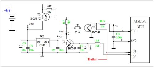
▲ Simplified breaker circuit diagram
Before turning on circuit. The "TEST" switch is off and MCU is not powered through VCC. At this time, T1 base is grounded through R9 (100kΩ) and is in off state. The test connected to base resistor R7 of T3 and T1 is in cutoff state, so T3 is also in cutoff state.
The +9V of power supply is isolated to T3 and is not loaded on voltage regulator IC IC2, and the VCC output of IC2 remains low.
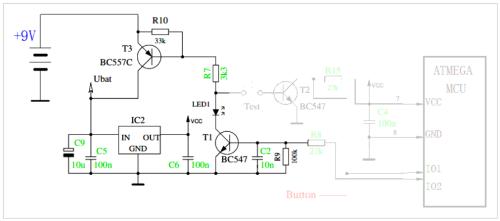
▲ Closed circuit status
Press "TEST" button to start circuit, base of T3 is grounded through R7, Test, b-e T2, so that T3 turns on. At this time, +9V is added to voltage regulator IC IC2 via T3. An IC2 VCC output is added to microcontroller.
After MCU is running, it outputs a high voltage through IO2 and turns on T1 through R8. Even if a test is run at this time, base of T3 can be grounded through R7, LED1 and T1 to open electric lock.
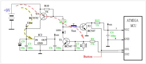
▲ Press TEST to run circuit
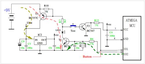
▲ After starting circuit, MCU provides base voltage T1 to maintain T3 conduction
The microcontroller software can then pull IO2 low again to disable T1 and then T3.
You can read state of T2 switch according to IO1 port and then determine if user has pressed a function key. After determining that user presses Test, after user releases Test, IO2 can be set to low.
According to software function, it can also automatically delay power off, thus reducing power consumption.
Related
- Analysis of power circuit of a classic single-chip microcomputer
- Analysis of damping RC circuit of a switching power supply "haberdashery"
- Detailed analysis of the "various protection schemes" of a switching power supply
- Experience in recognition of circuit diagrams of electronic circuits and method of circuit analysis
- Principal analysis of BUCK / BOOST circuit, a summary is also in place
- Analysis of various losses inside a switching power supply from 4 aspects
- What does inside of a multilayer PCB look like? Three-dimensional general analysis of design process of high-quality printed circuit boards
- Circuit Analysis of 6 Examples Explaining Lightning Surge Protection in Detail
- Analysis and comparison of 6 most commonly used DC power supply circuits
- What is a delay scheme? Explanation of 6 Kinds of Delay Circuit Principles
Hot Posts
 How to distinguish induction from leakage, we will teach you three tricks! Ordinary people can also learn super practical
- What is drowning in gold? Why Shen Jin?
- This is a metaphor for EMI/EMS/EMC that can be understood at a glance.
- How many types of pads have you seen in PCB design?
- Summary of Common PCB Repair Techniques
- What is three anti-paint? How to use it correctly?
- Knowing these rules, you will not get confused looking at circuit diagram.
- How to make anti-interference PCB design?
- Can diodes do this?