Location:Home Page > Archive Archive
Typical way to connect optocoupler isolation in a switching power supply
2023-12-07【Archive】
In general, isolated power supplies, optocoupler isolation feedback is a simple and inexpensive way. However, there is no in-depth research into various connection methods and feedback differences of optocouplers. Moreover, in many cases, due to a lack of understanding of working principle of an optocoupler and confusion about method of connecting an optocoupler, circuit often does not work normally. This study will analyze in detail working principle of an optocoupler and compare and study several typical optocoupler feedback connection methods.
1. Typical connection method and how it works
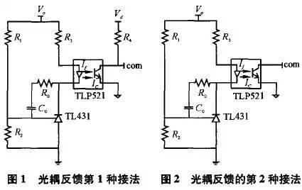
Models of optocouplers commonly used for feedback include TLP521, PC817, etc. Here, TLP521 is taken as an example to familiarize you with characteristics of this type of optocoupler. The primary side of TLP521 is equivalent to an LED. The larger current If of primary side, stronger light intensity and larger current Ic of secondary transistor. The ratio of secondary triode current Ic to primary diode current If is called current gain of optocoupler, which is temperature dependent and highly temperature dependent. The optocoupler used for feedback must implement feedback using "change in primary side current will cause change in secondary side current". Therefore, in case of serious changes in ambient temperature due to relatively large temperature drift of gain, it should not be maximally realized through optocoupler, feedback. In addition, when using this type of optocoupler, it is necessary to pay attention to design of peripheral parameters so that it operates in a relatively wide linear bandwidth, otherwise sensitivity of circuit to operating parameters will be too strong, which does not contribute to stable operation of circuit. Typically, TL431 is chosen for feedback in combination with TLP521. At present, working principle of TL431 is equivalent to a voltage error amplifier with an internal reference of 2.5V, so compensation circuit must be connected between pins 1 and 3. The first way to connect common optocoupler feedback is shown in Figure 1. In Figure 1, Vo is output voltage, and Vd is supply voltage of microcircuit. The link signal is connected to output pin of chip error amplifier, or internal voltage error amplifier of PWM chip (such as UC3525) is connected as a non-inverting amplifier, and link signal is connected to corresponding non-inverting amplifier. reversal of terminal pin. Note that ground on left is output voltage ground and ground on right is IC supply voltage ground, and they are isolated by an optocoupler. The principle of operation of connection shown in Figure 1 is as follows: when output voltage rises, voltage on pin 1 of TL431 (equivalent to reverse input pin of voltage error amplifier) rises, and voltage on pin 3 (equivalent tovalence voltage error amplifier) Amplifier output pin) voltage drops, primary current If TLP521 optocoupler increases, output current Ic of other end of optocoupler increases, The voltage drop across resistor R4 increases, comp voltage decreases, duty cycle decreases, output voltage decreases, on contrary, when output decreases voltage regulation process is similar. The second common connection method is shown in Figure 2. The difference from first connection method is that in this connection method, fourth pin of optocoupler is directly connected to output terminal of error amplifier of chip, and voltage error amplifier inside chip must be connected so that potential of non-inverting terminal is higher than that of inverting terminal. Form using characteristic of op-amp - when output current of op-amp is too large (more than current output of op-amp), output voltage value of op-amp will drop, and larger output current, more output voltage drops. Therefore, for a circuit using this connection method, two input pins of error amplifier of PWM chip must be connected to a fixed potential, and potential of same pin must be higher than potential of return terminal, so that initial output voltage of error amplifier is high.
 decreases if it increases. For a power supply system, changing loop gain can lead to instability, so it is inappropriate to set a static operating point at a place where If is too large (so that output characteristics saturate easily). It should be noted that Ic-If curve changes with temperature, but a change in temperature affects Ic value at a certain If value and generally does not affect Ic-If ratio. what's in fig. 7, except that curve generally shifts downward as temperature rises, as seen from Ic-Ta curve (as shown in Fig. 8).
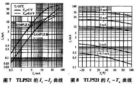
It can be seen from Figure 8 that when If is greater than 5 mA, Ic-Ta curves are basically parallel to each other.
2. Sample Compound Analysis
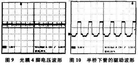
According to above analysis, below is a comparison of characteristics and scope of various typical connection methods. This study uses a real isolated half-bridge auxiliary power supply and a flyback power supply as examples. In first connection method, voltage connected to output of voltage error amplifier is obtained after external voltage is lowered by resistor R4, and is independent of current output power. voltage error amplifier. Operation of optocoupler The point selection can be adjusted as desired through its external resistance. According to previous analysis, static value of current operating point If is about 10mA, and corresponding operating temperature of optocoupler varies from 0 to 100 ° C, and value is from 20 to 15mA. As a rule, amplitude of triangular wave of PWM chip does not exceed 3V, so size of resistor R4 is chosen to be 670 ohms, and at same time, value of static operating point of 3-pin voltage of TL431 is determined to be 12V, so value of resistor R3 can be chosen to be 560 ohm. The values of resistors R1 and R2 are easy to choose, here they are 27k and 4.7k. Resistor R5 and capacitor C1 are PI compensators, here 3 kΩ and 10 nF. In experiment, output load of half-bridge auxiliary power supply is all kinds of control chips on control board, plus static load of each channel in multi-channel output, final actual power is about 30W. The actual measured voltage at pin 4 of optocoupler (this voltage is compared to triangular wave of chip to determine duty cycle) is shown in Figure 9. The corresponding control waveform is shown in Figure 10. The form of control signal in fig. 10 has a negative voltage part because excitation of upper and lower tubes is wound around driving magnetic ring. It can be seen that duty cycle of control signal is relatively large, about 0.7.
For second connection method, voltage error amplifier inside IC typically has a maximum output current of about 3 mA. If current value exceeds this value, maximum output voltage of error amplifier will drop. Therefore, in this regard, if duty cycle of power supply in steady state is large, current Ic is relatively small, and its value can only slightly exceed 3mA. According to Figure 7, Ib is about 2mA. Figure 6 shows that when value of Ib is small, a small change in Ib will cause a sharp change in Ic, and gain of optocoupler is very large, making it difficult to work with a closed network. stabilize. And if steady duty cycle of power supply is relatively small, voltage at pin 4 of optocoupler is relatively small, and output current of corresponding voltage error amplifier is relatively large, that is, Ic is relatively large. (much larger than 3mA), and corresponding Ib is relatively large, and same as in Figure 6, when Ib value is large, corresponding optocoupler gain is relatively moderate, and feedback network is relatively easy to stabilize.
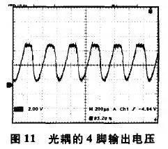
Similarly, for half-bridge auxiliary power supply circuit above, use connection 2 instead of connection 1, and closed loop is unstable. Use an oscilloscope to observe voltage waveform on pin 4 of optocoupler, and this is obvious. hesitation. The output voltage at pin 4 of optocoupler (corresponding to output pin voltage of error amplifier UC3525), waveform is shown in Figure 11, and obvious fluctuations can be detected. This is because steady-state duty cycle of half-bridge power supply is relatively large. According to connection method 2, gain of optocoupler is large, and system is unstable and fluctuates.
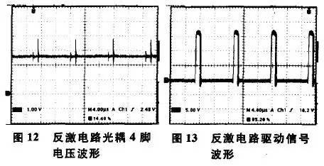
In fact, second connection method is more common in flyback circuit. This is because flyback scheme tends to go beyond efficiency considerations. The circuit usually operates in intermittent mode and duty cycle is relatively short. The corresponding optocoupler The current Ic is relatively large. Referring to above analysis, it can be seen that closed loop is relatively easy to stabilize. Below is another experimental flyback circuit that operates in discontinuous mode and actually measures voltage waveform at pin 4 of optocoupler as shown in Figure 12. The actual measured drive waveform is shown in Figure 13 and duty cycle is is about 0.2.
Therefore, when designing feedback of an optocoupler, in addition to tuning its peripheral parameters in accordance with characteristic parameters of optocoupler, one should also be aware that choice of feedback methods at various duty cycles is also limited. Feedback methods 1 and 3 are suitable for any duty cycle, while feedback methods 2 and 4 are more suitable for use in cases where duty cycle is relatively small.
3. Conclusion
This study lists 4 typical optocoupler feedback connection methods, analyzes optocoupler feedback principle under various connection methods and various limiting factors, and compares differences of various connection methods. Through actual testing of half-bridge and flyback circuit, it has been confirmed that duty cycle of circuit works with limited feedback mode selection. Finally, feedback of optocoupler is summed, which has some reference value for future optocoupler feedback design.
Related
- Typical way to connect optocoupler isolation in a switching power supply
- Engineer Daniel tells you: The "Y Capacitor" of a switching power supply is calculated in this way.
- Explain in detail why a switching power supply should be connected to an equivalent load.
- Finally, it becomes clear that process of obtaining switching losses of a MOSFET in a switching power supply
- How to choose a switching power supply - isolated or non-isolated
- Four ways to reduce the output "ripple and noise" of a switching power supply
- (In-depth long text) Detailed interpretation of switching power supply circuit
- Analysis of damping RC circuit of a switching power supply "haberdashery"
- Detailed analysis of the "various protection schemes" of a switching power supply
- Analysis of various losses inside a switching power supply from 4 aspects
Hot Posts
 How to distinguish induction from leakage, we will teach you three tricks! Ordinary people can also learn super practical
- What is drowning in gold? Why Shen Jin?
- This is a metaphor for EMI/EMS/EMC that can be understood at a glance.
- How many types of pads have you seen in PCB design?
- Summary of Common PCB Repair Techniques
- What is three anti-paint? How to use it correctly?
- Knowing these rules, you will not get confused looking at circuit diagram.
- How to make anti-interference PCB design?
- Can diodes do this?