Location:Home Page > Archive Archive
Power Knowledge - Flyback Transformer Design Process
2023-03-18【Archive】
Power Options
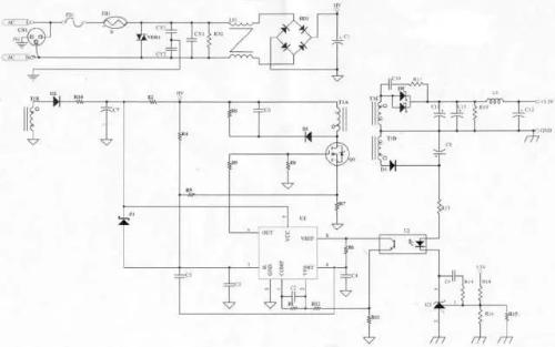
Depending on power, input and output conditions, we choose flyback power supply topology.
Flyback transformer advantages:
1. The circuit is simple and can effectively provide multiple DC outputs, so it is suitable for multiple output requirements.
2. High conversion efficiency and low loss.
3. The transformation ratio of transformer is small.
4. When input voltage fluctuates over a large range, it can have a relatively stable output signal.
Design steps:
1.Determine parameters of power supply.
2. Calculate circuit parameters.
3. Choose your base material.
4. Select shape and size of magnetic circuit.
5. Calculate number of turns of transformer, effective air gap inductance and air gap length.
6. Select diameter of winding coil wire.
7. Calculate transformer losses and temperature rise.
Scheme
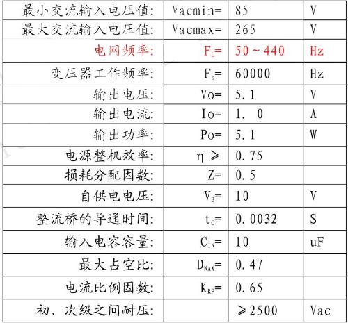
Step 1. Define power supply parameters: (some parameters are set by indicators, and some parameters are obtained from data)

Note. Current Scaling Factor: Ripple scale, ratio of ripple current to actual current at high and low load.
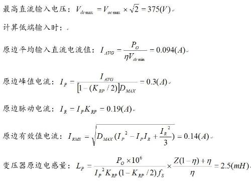
Step 2. Calculate circuit parameters:
Minimum DC input voltage:
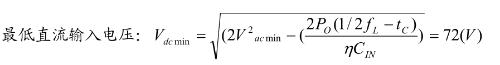
Z is loss distribution factor. If Z=1.0, this means that all losses are on secondary side. If Z=0, this means that all losses are on primary side. Here Z=0.5 means that there are losses on both primary and secondary sides.
Step 3. Choose your main material:
Ferrite material has characteristics of high resistivity and low high-frequency loss, and there are many kinds of materials and magnetic core specifications to meet different requirements. In addition, price is lower than other materials. It is currently most widely used material in pulse power sources. At same time, it also has disadvantages of relatively low saturation magnetic induction, material brittleness, poor impact resistance, and poor temperature performance.
The power ferrite material used is MnZn PC40, used for switching power transformers and high power transmission devices, with an initial magnetic permeability of 2300±25% and a saturation magnetic flux density of 510mT (at 25°C)/390mT. (100°C), Curie temperature 215°C.
Select PC40 as core material.
Step 4, choose shape and size of magnetic core:
Magnetic materials are indispensable in power high-frequency electronic circuits. Magnetic materials are mainly used in transformers and chokes (including resonant inductors) in circuits.
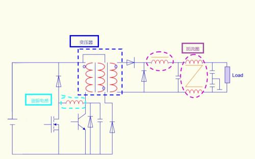
The transformer is an important core of entire power supply, so calculation and verification of transformer is very important.
Magnetic materials have problem of magnetic saturation. If magnetic circuit is saturated, it will cause distortion in power transmission of transformer, which will reduce inductance of inductor. For a power supply, reducing effective inductance will increase output ripple of power supply, and peak current through switch tube will increase. This may cause operating point of switch tube to exceed safe operating area, resulting in shortened switch tube life or damage. Another problem with magnetic materials is Curie point temperature.
(Curie temperature). At this temperature, magnetic properties of material change dramatically. In particular, material turns from ferromagnetic to paramagnetic, i.e., magnetic permeability rapidly decreases by several orders of magnitude. In fact, it becomes almost equivalent to an air core. The Curie point of some ferrites can reach 130°C. Therefore, we must pay attention to operating temperature of magnetic material.
Simply put, there are two questions:
Saturation - causes a decrease in inductance
Curie temperature - magnetic permeability decreases
Therefore, when choosing a transformer, we need to fully consider two issues:
1. The magnetic flux must be satisfied to avoid saturation.
2. The temperature should not be too high.
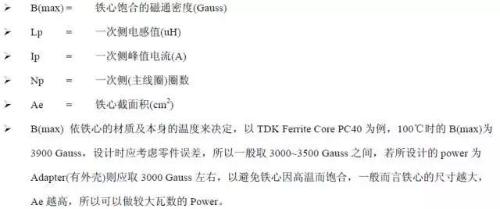
So, we need to calculate maximum value B(max) of magnetic flux of magnetic saturation of transformer core
Determine material and size of transformer:
According to transformer calculation formula
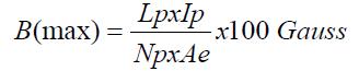
The calculation result of B(max) should not exceed rated value of iron core we have chosen, and should be reduced, and effect of poor heat dissipation caused by sheath should be taken into account, and a margin should be left.
There are two algorithms for B(max),
Area multiplication method (AP method)
Method of geometric parameters (KG method)
The output process is complex and cumbersome, so it will not be described in detail here.
The area product formula is used here to approximate shape and size of transformer core. The specific formula looks like this:
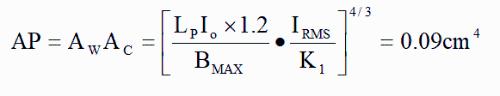
The flyback transformer operates in first quadrant, and there must be a margin for highest magnetic field density, so B=0.3T is chosen, and flyback transformer coefficient is K=0.0085 (K1 is current density of flyback transformer in free cooling. Empirical value 420 A/cm)
Magnetic core model: check EPC magnetic core series - EPC19, magnetic core parameters:
EPC cores are mainly designed for planar transformers, which have characteristics of a long center column and low leakage inductance. The AP value of EPC19 magnetic core is about 0.11 cm4, which is slightly higher than required AP=0.09 cm4 for calculation. If an EFD15 magnetic circuit with smaller dimensions is selected, its AR value is about 0.047 cm4, which is less than AR = 0.09 cm4 required for calculation, which does not meet requirements, therefore, ERS19 magnetic circuit is selected.
Step 5. Calculate number of turns of each winding of transformer, effective air gap inductance and air gap length:
1. Faraday's law of electromagnetic induction
The magnitude of induced electromotive force in a circuit is proportional to rate of change of magnetic flux passing through circuit
Ohm's law equation for inductance: V=L*(dI/dt)
So, we get an equation of current type:
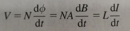
N*A*B=L*I
Number of turns of the primary winding:
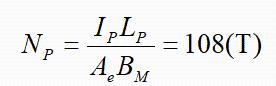
When inductance, current, number of turns and area are determined, magnetic saturation density is also determined.
In other words: in order to achieve a certain density of magnetic saturation, we need to increase number of turns to achieve it.
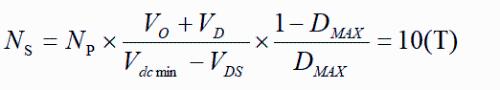
When number of turns on primary side meets requirements, we can calculate number of turns on secondary side through ratio of turns ratio.
Step 6. Select winding wire diameter:
In order to satisfy magnetic flux, we must also consider issues of current and space.
Determine diameter and number of wires of transformer:
When transformer is defined, bobbin (frame) of transformer can be defined. According to width of slit of bobbin (framework), wire diameter and number of wires of transformer can be determined, as well as current. The density of wire diameter can also be calculated. The current density is usually 6A/mm2. end.
Transformer frame effective width:
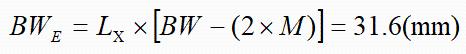
L is number of primary winding layers, 4 layers are used here.
M is required creepage distance at each end of coil, which here is 2mm.
(Creepage distance is shortest path between two conductive parts, or between a conductive part and equipment guard interface, measured along an insulating surface.)
Width of carcass winding: Bw=11.9 mm
Calculate maximum allowable primary wire diameter (enamelled wire):
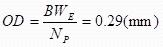
According to above calculation data, enameled wire with a bare wire diameter DIA=0.23 mm can be used for winding.
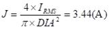
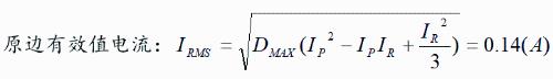
Calculate current density of primary winding according to selected wire diameter:
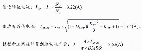
Calculate maximum allowable secondary wire diameter (enamelled wire):
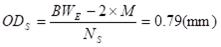
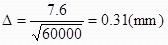
According to above calculated data, enameled wire with a bare wire diameter DIASS=0.72mm can be used for winding, but due to thickness of skin layer of copper wire at a temperature of 100°C and an operating frequency of 60 kHz:< br>
But thickness of 0.72mm is more than 2 times thickness of skin layer, which reduces utilization rate of copper wires, so two enameled wires with a diameter of 0.35mm are used and wound together.
Self-powered winding wire diameter: Since self-powered winding current is very small, only 5 mA, wire diameter requirements are not very strict. Here focus is on providing a better connection with secondary and mechanical strength, which is why it is also used. Enamelled wire with a bare wire diameter of 0.35 mm is wound so that it is simply wound in one layer to reduce leakage inductance with secondary winding and provide supply voltage. decreases in event of a short circuit.
Step 7. Calculate transformer losses and temperature rise
Transformer losses mainly consist of two parts: coil losses and magnetic core losses, which are calculated separately as follows:
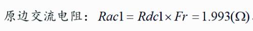
1) Coil loss:
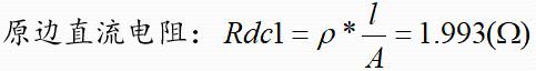
is specific resistance of copper at 100°C, 2.3×10⁻⁶ (cm), length of primary winding, measured 360 cm, A is cross-sectional area of the primary winding. Enamelled wire 0.23 mm.
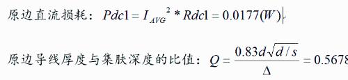
d is diameter of original enameled wire 0.23 mm, s is distance between centers of wire 0.27 mm, skin depth is 0.31 mm.
The ratio of AC resistance to DC resistance on primary side: Since winding method is used on primary side, number of winding layers on primary side can be considered as two layers and can be obtained according to Q value. obtained from above formula.
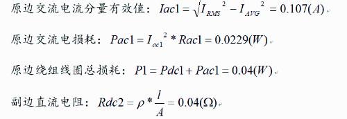
is resistivity of copper at 100°C, 2.3×10⁻⁶ (cm), length of secondary winding, measured 80 cm, A is cross-sectional area of two 0.38 mm enamelled wires on secondary side.
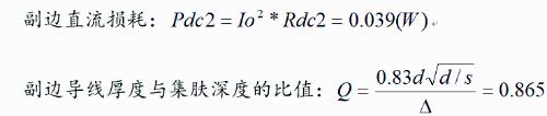
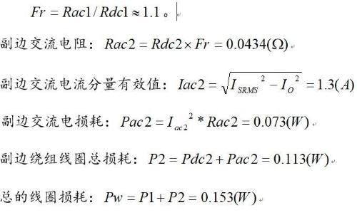
d — secondary enameled wire diameter 0.35 mm, s — distance between wire centers 0.41 mm, skin depth 0.31 mm. The ratio of AC resistance to DC resistance of secondary side: number of layers of secondary winding is one layer. From Q value obtained from above formula, you can find:
2) Losses in magnetic core:
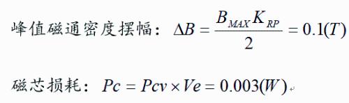
Pcv is power loss of magnetic core. It can be found in manufacturer's manual that losses are about 30 mW/cm3 due to peak flux density swing, operating frequency of 60 kHz and operating temperature of 100°C.
Ve is volume of EPC19 0.105 cm3.
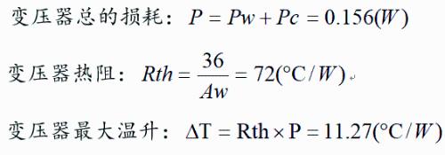
Conclusion: According to above calculation, at an ambient temperature of 85°C, maximum temperature of transformer is about 96°C, which corresponds to optimal operating temperature of magnetic core. At same time, winding method is used to ensure that leakage inductance is only 70uH (at 1kHz) / 15uH (at 100kHz), which is less than 3%, and effect is perfect.
Related
- Power Knowledge - Flyback Transformer Design Process
- Notes on whole switching power supply design process!
- The best switching circuit design process for power supplies is a must for engineers!
- PCB design guidelines: safety regulations, layout and wiring, EMC, thermal design, process engineering.
- Switching Power Supply PCB Design Skills
- Do not underestimate "form of high-frequency magnetic core" in switching power supply, what effect does it have on transformer?
- [Comic] Detailed explanation of knowledge of power sources
- Super practical! The 10 Most Commonly Used Power Supply Design Formulas
- The most complete knowledge in history of uninterruptible power supply UPS
- 6500 words about switching power supply design, haberdashery, collect first, then study!
Hot Posts
 How to distinguish induction from leakage, we will teach you three tricks! Ordinary people can also learn super practical
- What is drowning in gold? Why Shen Jin?
- This is a metaphor for EMI/EMS/EMC that can be understood at a glance.
- How many types of pads have you seen in PCB design?
- Summary of Common PCB Repair Techniques
- What is three anti-paint? How to use it correctly?
- Knowing these rules, you will not get confused looking at circuit diagram.
- How to make anti-interference PCB design?
- Can diodes do this?