Location:Home Page > Archive Archive
Understanding oscilloscope bandwidth is easy
2023-08-21【Archive】
01Oscilloscope bandwidth overview --- rise time and waveform accuracy
When oscilloscope users choose an oscilloscope for basic measurements, oscilloscope's basic parameters are often only criteria for choosing an oscilloscope. Main index parameters of oscilloscope:
(1) bandwidth;(2) sample rate;(3) record length.
Bandwidth. What does this indicator say?
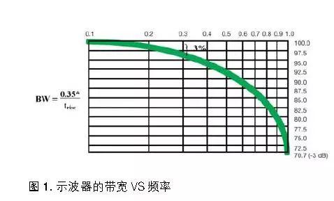
Analog bandwidth is a measure of measurement. Simple definition: highest frequency at which amplitude of a sine wave measured by an oscilloscope is at least 3 dB of actual sine wave amplitude (see IEEE-1057). As shown in Figure 1, this is a graph of ideal oscilloscope bandwidth and amplitude measurement error. Figure 1 shows that when frequency of measured sine wave is equal to bandwidth of oscilloscope (the response amplifier of oscilloscope is a first-order Gaussian type), amplitude measurement error is about 30%. If you want to measure a sine wave with an amplitude error of only 3%, frequency of measured sine wave must be much lower than oscilloscope bandwidth (about 0.3 times oscilloscope bandwidth). Since most signals are much more complex than a sine wave, a general rule of thumb for measuring signals with an oscilloscope is that bandwidth of oscilloscope is five times frequency of the signal being measured.
Bandwidth - don't say anything?
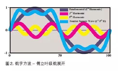
The most typical user chooses an oscilloscope to display and measure complex electrical and optical signals, and observes display of signal amplitude versus time on oscilloscope. Analog bandwidth, an important oscilloscope metric, must be defined in frequency domain, not time domain. According to sampling theory, complex signals contain rich spectral components in frequency domain (including harmonic components of several sine waves), as shown in Figure 2. However, using spectrum analysis, you can see frequency components of sampled signal, if you want to fully characterize these frequency components, you need to know exact amplitude and phase information of each component that makes up complex signal. In this case, bandwidth tells us nothing more than how those details will be captured. In terms of bandwidth measurement, we only know that if a sinusoidal signal with same frequency and bandwidth is input, amplitude measurement error of oscilloscope is 30%.
What is relationship between bandwidth and rise time?
In addition to general signal analysis, most engineers are also interested in timing measurements such as rise and fall times of square waves. Therefore, rise time of an oscilloscope system can be estimated from specified bandwidth, we can use following formula: tr = 0.35/BW (or 0.42/BW), namely:
BW=0.35/tr (or 0.42/tr)=5*Fclock (tr=7%*T of regular signals, where: T=1/Fclock). Actual Signal Bandwidth: The harmonic frequency when signal harmonic amplitude will be 70% of wave 0 (fundamental) (i.e. 3 dB drop).
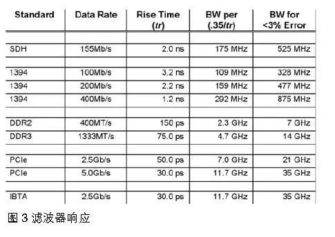
Here, 0.35 is proportional factor between oscilloscope bandwidth and rise time (10% to 90% rise time in a first-order Gaussian model). Most oscilloscope amplifiers use a first-order Gaussian. RC low pass filter response model. It is easy to calculate rise time tr from this formula, but this is often not case. The table in Figure 3 provides recommendations for measurement system bandwidth required for various signal standards. The recommended system bandwidth may provide sufficient accuracy for rise time measurements or other measurements. Note that accuracy of oscilloscope rise time results can be affected by many measurement system factors, including signal source, probe, and oscilloscope. In table in fig. Figure 3 assumes that both signal and oscilloscope test system have first-order response characteristics, but in reality, especially for today's high-speed serial signals, this assumption is far from reality. For flattest envelope delay response, ratio between bandwidth and rise time of an oscilloscope is close to 0.45. Figure 3 shows that rise time and bandwidth proportionality change, and 20 GHz frequency response model also changes from a simple first order response to a 32nd order response. The 16th and 32nd order responses are similar to today's high performance oscilloscopes, and tr/BW ratio of these high performance oscilloscopes is close to 0.4 or 0.45. For this scale factor, oscilloscope's frequency response is very flat from low frequencies to cutoff frequency of oscilloscope's bandwidth. Also, if a very good filter is used in instrument, its amplitude and phase will be well compensated to capture and analyze complex signals with best possible accuracy. What is really best oscilloscope? Two oscilloscopes with same bandwidth can have different rise times, as well as different frequency and phase characteristics! Therefore, knowing only bandwidth of oscilof a logograph, one cannot reliably know its measurement capabilities or its ability to accurately capture complex signals such as high-speed serial data streams. At same time, it is debatable whether true rise time of oscilloscope is consistent with rise time calculated from oscilloscope bandwidth. The only reliable way to get true rise and fall times of an oscilloscope is to measure an ideal step signal with a much faster rise time than an oscilloscope.
02Probe bandwidth and rise time
BandwidthTo meet design requirements of oscilloscope probes, probe bandwidth is a wide frequency range. For example, a 100 MHz oscilloscope probe requires a frequency range to be measured up to 100 MHz, and probe can capture signal changes in specified frequency range. In fact, every probe manufacturer considers that probe's frequency response is 3dB lower at maximum specified bandwidth. At frequencies above 3 dB, signal amplitude will be severely attenuated and measurement results may be unpredictable. The principle of accurate amplitude measurement is as follows: bandwidth of measuring system should be more than 3-5 times frequency of measured signal. This recommendation provides sufficient bandwidth to capture high frequency content of non-sinusoidal signals such as square waves. For example, a measurement system with a bandwidth of 300 MHz to 500 MHz is recommended for capturing a 100 MHz square wave.
The bandwidth is shown in Figure 1. As frequency increases, amplitude of signal decreases. As mentioned earlier, loss of amplitude within 3 dB of bandwidth specified by probe manufacturer has no obvious effect on test signal. square wave... When using a probe to test a signal, probe bandwidth should be chosen so that it is more than 3 to 5 times frequency of signal under test, and amplitude error decreases from 30% at 3 dB to about 3%.
Rise timeBandwidth describes characteristics in frequency domain, but does not give a complete picture of how a probe, an oscilloscope, reproduces complex waveforms over time. To fully understand process of reproducing a waveform, it is necessary to obtain transient response to obtain characteristics in time domain. The time domain characteristics are characterized by rise time of probe, and a step signal much faster than test system is introduced to estimate system's step response, thus obtaining rise time. As a general rule, when choosing a probe, rise time of probe should be 3 to 5 times longer than rise time of signal being measured.
Oscilloscope sample rate
A common unit for digital storage oscilloscope sampling rate is 1 GS/s. What does this mean?
samples 1G points per second. However, sampling rate of a digital oscilloscope is not fixed, and number of samples per second depends on screen resolution. 1G refers to maximum sampling value.
Record Length
Record length = sample raterefresh rate × refresh rate × 10.
Related
- Understanding oscilloscope bandwidth is easy
- With these two schematics, PCB design is easy!
- How to effectively use an oscilloscope? Even senior engineers overlook these details...
- A simple understanding of op amps...
- Understanding input impedance and output impedance
- Deep Understanding of Analog Electronics - Analog Electronics Tutorial
- One Article for Understanding PFC (Power Factor Correction)
- Easy to understand! Explain PID
- "Easy to understand" Miller effect when switching MOS lamps
- How many of these free and easy to use circuit design programs have you used?
Hot Posts
 How to distinguish induction from leakage, we will teach you three tricks! Ordinary people can also learn super practical
- What is drowning in gold? Why Shen Jin?
- This is a metaphor for EMI/EMS/EMC that can be understood at a glance.
- How many types of pads have you seen in PCB design?
- Summary of Common PCB Repair Techniques
- What is three anti-paint? How to use it correctly?
- Knowing these rules, you will not get confused looking at circuit diagram.
- How to make anti-interference PCB design?
- Can diodes do this?