Location:Home Page > Archive Archive
Senior EMC Engineer Resume: EMC Troubleshooting Process and Common Problems
2023-03-18【Archive】
EMC is mainly achieved through a comprehensive assessment of electromagnetic interference and immunity of product under test, and is one of important indicators of product quality and safety certification. Many products will be subject to unqualified product testing in product safety certification, especially in EMC test (ie EMC test), error rate is more common. After product fails test, an EMC correction notification must follow. In process of EMC elimination, many managers and technicians are not quite sure where to start. Today we will analyze problems that often occur during EMC elimination and some suggestions for correction.
First of all, let's start with composition of EMC test items. EMC mainly includes two elements: EMI (interference) and EMS (anti-interference and product sensitivity). Of course, these two main elements include many small elements. The main elements of EMI test are: RE (product emission), CE (product conducted), Harmonic (harmonic), Ficker (flicker). Main elements of EMS test: ESD (product static electricity), EFT (transient transient), DIP (voltage drop), CS (conduction anti-interference), RS (radiative anti-interference), Surge (lightning strike), PMS (magnetic field immunity). With these test items, it is easy to see that EMC test mainly focuses on EMI and sensitivity of product. If product does not meet safety certification standards and needs EMC correction, we can fix it by reducing its materials. and components.
First, EMC's opinion on bug fixes
1. After receiving a proposal for a correction, an EMC correction plan must be posted in advance. Blindly fixing products without a good positioning plan is like a headless fly that will only add to cost of fix.
2. The positioning of means for editor here, I think, can be divided into two main points. First: Intuitive judgment must rely entirely on intuition and experience of engineers. Second: benchmarking, problem analysis according to data provided by test tool.
2. EMC elimination process
1. RE:
exceeding standards process 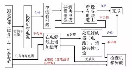
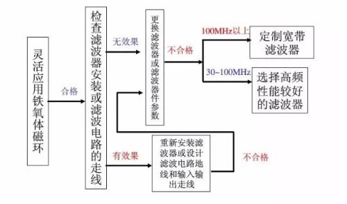
2. Process for fixing wires and cables that exceed standards:
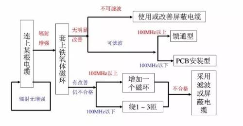
3. Signal cable repair process:
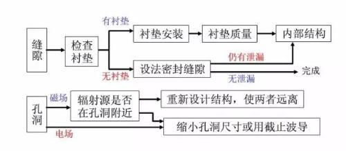
4. Screen leak repair process:
Third, a few small EMC suggestions
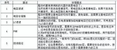
1. The filtering effect of capacitors
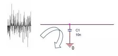

That is, higher frequency f, lower impedance Z of capacitor.
At low frequency, due to relatively large impedance Z of capacitor C, useful signal can pass unhindered;
At high frequency, capacitance C is already very small due to impedance Z, which is equivalent to short circuiting high frequency noise to GND.
2. When will capacitive filtering stop working?
Rectifiers often use components such as capacitors for filtering. It is often said that "large capacitors filter low frequencies and small capacitors filter high frequencies".
Let's take a conventional MLCC surface mount ceramic capacitor as an example. The equivalent model looks like this:
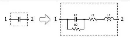
The parameters of X7R ceramic model with a capacitance of 10 nF in 0603 package are as follows:
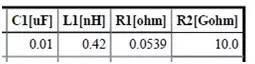
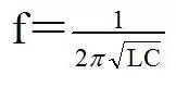
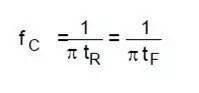
Because equivalent model has both capacitance C and inductance L, forming a second-order system, instability occurs. The circuit is in resonance and resonance point is at following frequency:
The image below shows an example of a resonance curve:
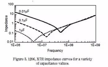
That is, it is a capacitor before resonance point and no longer a capacitor after resonance point.
3. When to use LC filter
If an inductor L is connected in series and then connected in parallel with form C, you get an LC filter:
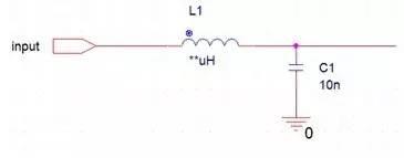
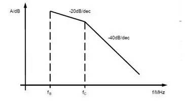
One capacitor C is a first order system and one inductor L is also a first order system, and slope of attenuation amplitude is -20dB. However, for a second-order system composed of LC, attenuation amplitude slope is -40 dB, which is closer to ideal "steep" cutoff frequency effect, i.e., the filtering effect is better.
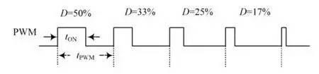
4. What is PWM frequency
PWM is often mentioned, for example, 20kHz PWM is used to drive a motor. But in fact, these 20 kHz only mean that PWM pulse period is 50 µs:
Then where frequency point of so-called PWM of 20 kHz falls into frequency domain, following formula:
For a step signal, since rise time tr is infinitely short, frequency f is infinitely large. When frequency is high, parasitic parameters cannot be ignored, which will cause many resonance problems.
From a signal point of view, a signal with a very steep pitch will have issues with glitches and jitter. Simply put, larger frequency f, wider frequency occupied by noise will be, i.e. worse EMC performance will be.
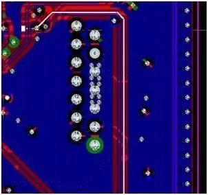
5. How to map a circuit diagram to a PCB
Due to problem of separation of work types, schematic diagram and PCB were separated, and division of work was carried out by two groups of people:

For example, circuit diagram has the following diagram:
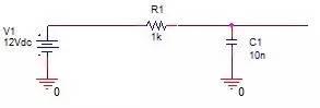
This means that problem is that there is actually a line between negative pole V1 and negative pole C1 on PCB (the word used in PCB layout software is more accurate: trace, trace/trace ).
A->B->C are often affected during design phase. If there is a problem with EMC, in addition to searching for circuit parameters on circuit diagram, you also need to pay special attention to C->D, that is, return path.
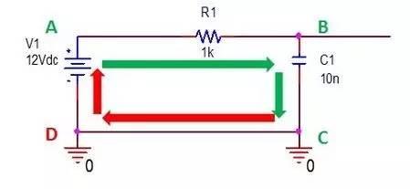
If return path is uneven, it will distort signal:
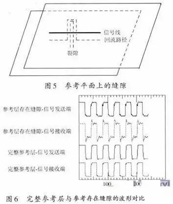
For example, during an EMC test, if signal collected by ADC of microcontroller is broken, in addition to analyzing it on circuit diagram, highlight signal on board, and then patiently look for return path of signal. Uneven places:
When you look at signal line and imagine way back, it's a bit like a stream of consciousness.
6. Resume
Related
- Senior EMC Engineer Resume: EMC Troubleshooting Process and Common Problems
- PCB design guidelines: safety regulations, layout and wiring, EMC, thermal design, process engineering.
- Diagram of relationship between PCB layout and EMC
- Suggested collection: Capacitor filtering analysis and EMC suggestions.
- Common USB Interface Circuit Design Problems and Solutions
- Senior engineer summarizes 10 methods for complex circuit analysis
- This is a metaphor for EMI/EMS/EMC that can be understood at a glance.
- Diode switching circuit and troubleshooting, one complete wizard
- What is a magnetic sensor? The most common types of magnetic sensors and their applications
- How to effectively use an oscilloscope? Even senior engineers overlook these details...
Hot Posts
 How to distinguish induction from leakage, we will teach you three tricks! Ordinary people can also learn super practical
- What is drowning in gold? Why Shen Jin?
- This is a metaphor for EMI/EMS/EMC that can be understood at a glance.
- How many types of pads have you seen in PCB design?
- Summary of Common PCB Repair Techniques
- What is three anti-paint? How to use it correctly?
- Knowing these rules, you will not get confused looking at circuit diagram.
- How to make anti-interference PCB design?
- Can diodes do this?