Location:Home Page > Archive Archive
ADC basics and comparative analysis of different ADC technologies
2023-05-08【Archive】
This world is both analog and often cut into digital fragments by us. As communications became more digitized and computing power increased, signals were converted into numbers that were easier to transmit and mathematically easier to calculate. The signal conversion process is an analog-to-digital process, which has led to advent of analog-to-digital converter (ADC).
The digital signal is synchronized to clock frequency. According to Nyquist criterion, sampling rate of ADC should be at least twice maximum frequency of analog input being digitized. This frequency is known as Nyquist sampling rate.
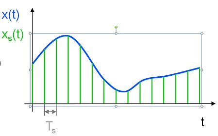
Figure 1. ADC sampling rate
As shown in Figure 2, quantization granularity (grain) of an ADC increases with increasing sample rate and resolution. The y-axis is resolution, which is actually number of ADC bits. The x-axis represents sampling rate.
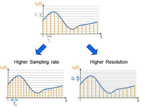
Figure 2. ADC accuracy depends on sample rate and resolution
The number of digits is defined as a power of 2. Therefore, an 8-bit ADC will have a resolution of 28 or 256 bits. For a simple example of a 3-bit ADC converter, its resolution is shown in ladder analogy of Figure 3, with y-axis showing 3-digit ADC code and x-axis showing signal voltage range and gain.
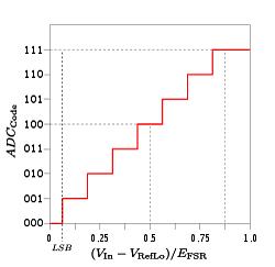
Figure 3: ADC digital code and input voltage
For those who are new to digital signals, you can look at it this way: using binary code "1" and "0" means simply treating a bit with a value of "1" as turning on a switch. , and a bit with a value of "0" as in a switch. It is very different from decimal number system based on number of fingers on our human hands. In electronic circuits, it is not easy to implement a ten-position switch. Consequently, focus was on switching transistors faster, resulting in a frenzy of high frequencies.
Several factors are taken into account when digitizing a signal. They cause errors such as quantization errors between voltage detection levels, and other errors include signal non-linearity.
The error is not limited to analog part of ADC. Noise and clock jitter also affect digital signals.
Different ADC types have different sources (of errors). The main types of ADCs are:
Flash ADC
Sigma-Delta ADC
Double Slope ADC
Successive approximation ADC
The choice of ADC is usually based on speed and accuracy. The more bits an ADC has, more accurate it will be, but slower it will be (because each bit adds one clock cycle). On fig. 4 compares speed and accuracy of various ADCs.
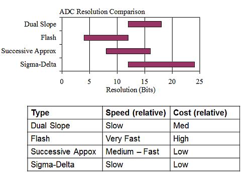
Figure 4. Comparison of different ADC technologies
Although ADCs are digital devices, a significant amount of analog technology is involved in interface of each ADC technology. Also, type of communication bus available can help in selection process, as many serial links have bandwidth or bit limits. As with any product, more performance and speed required, greater complexity and cost. This has led to an ever-expanding ADC market with ever-expanding applications, similar to sensor market. Similar to sensor market, with development of technology and improvement of functions, ADC is also constantly improved.
Related
- ADC basics and comparative analysis of different ADC technologies
- Summary of questions and answers on basics of analog circuits
- Experience in recognition of circuit diagrams of electronic circuits and method of circuit analysis
- Haberdashery|General failure mechanism and analysis of electronic components
- Analysis and comparison of 6 most commonly used DC power supply circuits
- Analysis of power circuit of a classic single-chip microcomputer
- Analysis of damping RC circuit of a switching power supply "haberdashery"
- Suggested collection: Capacitor filtering analysis and EMC suggestions.
- Detailed analysis of the "various protection schemes" of a switching power supply
- List of 5 Most Practical Network Analysis Techniques! must watch
Hot Posts
 How to distinguish induction from leakage, we will teach you three tricks! Ordinary people can also learn super practical
- What is drowning in gold? Why Shen Jin?
- This is a metaphor for EMI/EMS/EMC that can be understood at a glance.
- How many types of pads have you seen in PCB design?
- Summary of Common PCB Repair Techniques
- What is three anti-paint? How to use it correctly?
- Knowing these rules, you will not get confused looking at circuit diagram.
- How to make anti-interference PCB design?
- Can diodes do this?