Location:Home Page > Archive Archive
List of 5 Most Practical Network Analysis Techniques! must watch
2023-05-03【Archive】
A good study of circuit analysis is basis of subsequent courses. It's simple, but important. Only when you get good at circuit analysis will you have a good idea for solving problems in later courses.
Wiring diagram is a basic professional course. Compared to basic culturological courses, it is more focused on solving practical engineering problems. Compared to professional courses, it focuses more on physical concepts and general theoretical analysis.
Circuit theory is abstracted from real thing, and it is related to real thing, but also different from it, so special attention should be paid to conditions of use cases. Circuit courses have special rules and will be much easier to learn and remember once you learn rules.
Theoretical Circuit Analysis The first is to define model of circuit components, ie ideal resistance components, inductance components, and capacitance components. After mastering current-voltage characteristics of these components, many problems can be easily solved. .
It should be noted that principle followed by structure of circuit, that is, basic second law of Ehrhoff, is key to solving problem of structure of circuit. Analysis of calculations.
In order to correctly and simply analyze and calculate circuits, complex circuits must be simplified using equivalent transformation, which is main tool in circuit theory. Equivalence, this must be firmly grasped.
Read example questions carefully at usual time. The examples are an integral part of course content and link between concept and problem solving. A characteristic of schema textbooks is that laws, theorems, and principles are included in book as examples. Doing more exercises is also an important aspect of learning in circle classes. The exercises are an integral and important part of textbook, and doing exercises helps deepen your understanding of basic concepts. The exercises must not only be correct, but must understand concepts to be explored in each exercise, find out why question is being asked, and what content is being evaluated so that learning can be deep and good. Solving exercises is an extremely important part of developing your thinking skills, as well as a ruler to check if you really understood concept.
Distinguish between circuit models and real devices. Ideal circuit components are imaginary components scientifically abstracted from real circuit devices. Attention should be paid to relationship and differences between circuit components and real devices. Generic devices can be modeled with ideal circuit elements and their combinations, but they are not completely equivalent. For example, provided that frequency is not too high, mathematical model of coil is a series connection of resistance element and elementinductance, and at high frequency capacitive action between wires of coil winding cannot be ignored, in which case a more accurate model representing this coil should also include capacitive elements.
Highlight special tasks of analytical calculations in different areas. For analysis and calculation of circuit theory, form is not static. For example, current-voltage characteristics of ideal components used in calculation in time domain, as well as method expressed by structural characteristics, are not applicable in frequency domain. This gives us enlightenment. Any current-voltage characteristics, structural laws, principles and formulas used in calculation and analysis of a certain range must be taken into account when using it in another range. For special tasks, modify previous expressions, and solve these problems after processing, methods previously learned can be used in a new area. Schema analysis is constantly looking for ways to solve problems, so special attention is paid to conditions necessary for use in new areas. In short, if you want to learn circuit theory well, you must think more, calculate more, and do more.
List of five most practical circuit analysis techniques
1
Flowchart recognition method
Figure 1 shows a block diagram of a two-stage audio amplification system. It can be seen from figure that this system circuit is mainly composed of a signal source circuit, a first stage amplifier, a second stage amplifier, and a load circuit. From this block diagram, you can also understand that this is a two-stage amplifier circuit.
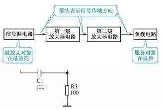
Figure 1. Schematic block diagram
2
Basic diagram recognition method
A single circuit refers to a certain level of controller circuit, a certain level of amplifier circuit, a certain oscillator circuit, a frequency converter circuit, etc. It is smallest circuit that can perform a certain circuit function. In a broad sense, an integrated circuit application circuit is also a single circuit.
In process of studying working principle of electronic circuit of whole machine, block diagram is first circuit diagram with a complete set of functions. The concept of this circuit diagram is entirely intended for convenience of analyzing principle of operation of circuit.
1. Schematic diagram of device
The device schema has following functions.
(1) Block diagram is mainly used to describe how circuit works.
(2) The circuit diagram of block can fully reflect structure and working principle of circuit of a certain level, and sometimes all parameters of each component in circuit, such as nominal resistance, nominal capacitance and transistor model, are noted. As shown in Figure 2, figure marks the resistance values of variable resistors and resistors.
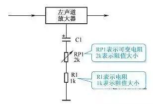
Figure 2 Schematic Diagram
(3) The circuit diagram of a block is very useful for a deep understanding of how circuit works, as well as structure and composition of memory circuit.
2. Features of circuit diagram of unit
The block diagram is mainly for convenience of analyzing working principle of a certain block diagram, and circuit diagram of this part of circuit is drawn separately, so other components and related connections that are not related to block diagram are not shown in figure. Therefore, circuit diagram of device is relatively is simple and clear, and there is no interference from other circuits when reading circuit, which is an important feature of device circuit. The power supply, input and output connectors are simplified on circuit diagram of device. On fig. 3 shows setup diagram.
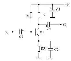
Figure 3. Schematic block diagram
(1) A way to represent a power source. In circuit diagram, +V is used to indicate DC operating voltage, where a positive sign indicates that positive DC voltage is used to power circuit, and ground terminal is connected to negative pole of power supply. ;-V is used to indicate DC operating voltage, where negative sign indicates that DC voltage of negative polarity is used to power power circuit, ground terminal is connected to positive pole of power supply.
(2) Methods for representing input and output signal. Ui represents input signal to be amplified or processed by this unit circuit; Uo represents output signal, which is signal amplified or processed by this unit circuit.
3
Branch node method
A node is a meeting point for several branches of a chain. The so-called branch node method is to number each node (the convention; positive pole of power supply is first node, and nodes passing in order from positive pole to negative pole of power supply are 1, 2, 3...), and branches, starting from first node Road, lead to negative pole of power source. There can be multiple branches (regulation: different branches cannot pass through same resistor multiple times), which can reach negative pole of power supply. The drawing principle is to first draw a branch with a small number of nodes, and then draw a branch with a large number of nodes. Then, following this principle, draw a branch, starting from second node. By analogy, for rest of time, finally draw remaining resistors according to positions of their two ends.
Example 5. Draw equivalent circuit shown in Figure 10.
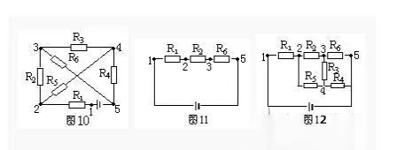
Decision. In Figure 10, there are five nodes 1, 2, 3, 4, and 5. According to principle of branch node method, there are two branches with a small number of nodes coming out of positive pole of power supply (node 1): branches R1, R2, R6 and branches R1, R5, R4. Take one of branches R1, R2, R6 and draw it as shown in Figure 11.
Starting from second node, there are two branches reaching negative pole, one is R5, R4, number of nodes is 3, other is R5, R3, R5, number of nodes is 4, and existing R6 cannot be repeated. Therefore, branches R5 and R4 must be drawn again, and finally remaining resistance R3 must be drawn, as shown in Figure 12.
4
Geometric deformation method
Geometric deformation is based on characteristics that wires in a circuit can be arbitrarily lengthened, shortened, rotated, or moved, etc., to geometrically deform a given circuit to further define interconnection of circuit components. , and draw equivalent circuit diagram.
Example 6. Draw a circuit equivalent to fig. 13.
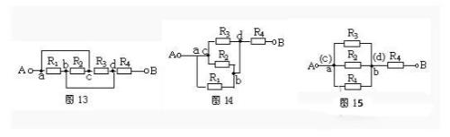
Solution: Shorten AC branch wires and deform circuit geometrically to get Figure 14, then compress ac to one point and bd to one point, making it clear that R1, R2 and R5 are connected in parallel. , and then sequentially with R4 (Fig. 15).
5
Remove resistance method
According to characteristics of series-parallel circuits, in a series circuit, if any resistor is removed and no current flows through other resistors, these resistors are connected in series; in a parallel circuit, if any resistor is removed, other resistors still carry current, and these resistors are then connected in parallel.
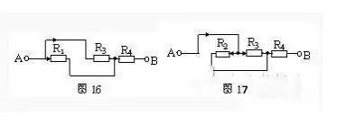
Still taking Figure 13 as an example, assuming current flows from terminal A and flows out from terminal B, remove R2 first, and Figure 16 shows that current flows through R1 and R3. By removing resistor R1, Figure 17 shows that current is still flowing through resistors R2 and R3. In same way, when resistor R3 is removed, current also flows through R1 and R2. It can be seen from characteristics of parallel circuit that R1, R2 and R3 are connected in parallel and then connected in series with P4.
Related
- List of 5 Most Practical Network Analysis Techniques! must watch
- You must learn drawing techniques and skills of 18 special circuit board routes.
- Analysis and comparison of 6 most commonly used DC power supply circuits
- Several Effective Circuit Analysis Techniques
- A list of most common PCB design mistakes, see how many mistakes have you made?
- The most complete test of iron 5 processes, one less will not work
- Summary of Common PCB Repair Techniques
- Super practical! The 10 Most Commonly Used Power Supply Design Formulas
- Analysis of power circuit of a classic single-chip microcomputer
- A list of some of the tools commonly used by electronic engineers.
Hot Posts
 How to distinguish induction from leakage, we will teach you three tricks! Ordinary people can also learn super practical
- What is drowning in gold? Why Shen Jin?
- This is a metaphor for EMI/EMS/EMC that can be understood at a glance.
- How many types of pads have you seen in PCB design?
- Summary of Common PCB Repair Techniques
- What is three anti-paint? How to use it correctly?
- Knowing these rules, you will not get confused looking at circuit diagram.
- How to make anti-interference PCB design?
- Can diodes do this?