Location:Home Page > Archive Archive
Ultra-detailed USB Type-C pin signal and familiarity with PCB layout
2023-09-01【Archive】
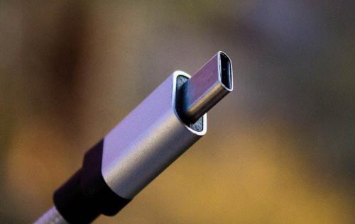
USB Type-C is a specification for a USB connector system that is gaining popularity in smartphones and mobile devices that can carry both power and data. Unlike earlier USB offerings, it's also reversible so you don't have to try to plug it in multiple times.
01 What is USB-Type-C
USB-C is a relatively new standard that provides high-speed data transfers up to 10Gbps and up to 100W of power. These features could make USB-C a truly universal connection standard for today's devices.
02 Feature Introduction
The USB-C interface has three main functions:
● It has a reversible connection port. The interface is designed in such a way that plug can be reversed relative to socket. ● It supports USB 2.0, USB 3.0 and USB 3.1 Gen 2 standards. In addition, it can support third-party protocols such as DisplayPort and HDMI in an operation mode called Alternate Mode. ● This allows devices to negotiate and select appropriate power flow through interface.
Signal 03 icon
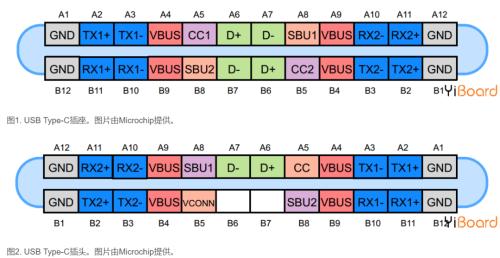
The USB Type-C connector has 24 pins. Figure 1 and Figure 2 show pins of USB Type-C connector and plug, respectively.
04 USB 2.0 differential pairs
The D+ and D- pins are a differential pair for USB 2.0 connections. The socket has two D+ pins and two D- pins. However, these pins are connected to each other, and in fact only one USB 2.0 differential data pair is available for use. The redundant design is only intended to provide reversible connectors.
05 power and ground pins
The VBUS and GND pins are return paths for power and signals. The default VBUS voltage is 5V, but standard allows device to negotiate and select a VBUS voltage other than default. The power supply accepts VBUS voltage up to 20V. The maximum current can also be increased up to 5A. Therefore, USB Type-C can provide a maximum power of 100W.
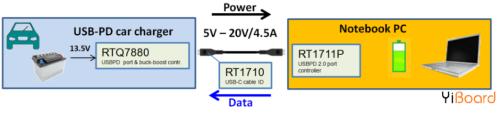
High power can be useful when charging large devices such as laptops. On fig. Figure 3 shows a RICHTEK example where a buck-boost converter is used to generate appropriate voltage required by laptop.
Note that Power Delivery technology makes USB Type-C more versatile than older standards as it tailors power levels to suit needs of load. You can charge your smartphone and laptop with same cable.
06 pins RX and TX
There are two sets of RX differential pairs and two sets of TX differential pairs. One of these two RX pairs along with a TX pair can be used for USB 3.0/USB 3.1 protocol. Because connectors are reversible, multiplexer must correctly reroute data on differential pair being used over cable.
Please note that USB Type-C ports can support USB 3.0/3.1 standards, but minimum USB Type-C feature set does not include USB 3.0/3.1. In this case, USB 3.0/3.1 connection does not use RX/TX pair and can be used by other USB Type-C features such as Alternate Mode and USB Power Delivery protocol. These functions can even use all available differential RX/TX pairs.
07 pins CC1 and CC2
These pins are channel configuration pins. They perform many functions such as cable plug and play detection, jack/plug orientation detection, and live broadcast. These pins are also used for communication required for power and alternate mode.
In fig. Figure 4 below shows how pins CC1 and CC2 show connector/plug orientation. In this diagram, DFP means a downstream port that acts as a host or power source when data is transferred. UFP stands for Upstream Facing Port, that is, a device connected to a host or power consumer.
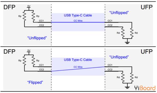
DFP pulls up pins CC1 and CC2 through resistor Rp, and UFP pulls them up through resistor Rd. If cable is not connected, source sees a high logic level on pins CC1 and CC2. Connecting USB Type-C cable creates a current path from 5V power supply to ground. Since there is only one CC wire inside USB Type-C cable, only one current path is formed. For example, in image above, CC1 pin of DFP is connected to CC1 pin of UFP. Therefore, voltage on DFP CC1 pin is below 5 V, but DFP CC2 pin is still high. So, by monitoring voltage on DFP pins CC1 and CC2, we can determine cable connection and its orientation.
Besides guiding cable, Rp-Rd path is also used as a means of conveying information about current capability of source. To do this, power consumption (UFP) monitors voltage on CC line. When voltage on CC line is at its lowest value (about 0.41V), source can provide default USB power of 500mA and 900mA for USB 2.0 and USB 3.0 respectively. With a CC line voltage of about 0.92 V, source can deliver 1.5 A. The maximum line voltage of CC is approximately 1.68 V, which corresponds to a source current of 3 A.
Contact 08 VCONN
As mentioned above, USB Type-C is designed to provide ultra-high data transfer rates combined with high levels of power flow. These functions may require use of special cables that are electronically marked with a chip embedded in them. Also, some active cables use re-driver ICs to amplify signal and compensate for losses caused by cable, etc. In these cases, we can power circuits inside cable by supplying 5V, 1W power to the VCONN pin. as shown below.
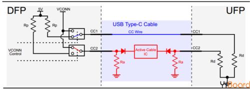
As you can see, active cable uses Ra resistor to turn off CC2 pin. Ra has a different value than Rd, so DFP can still determine direction of cable by checking voltage on DFP pins CC1 and CC2. After orienting cable, channel configuration pin corresponding to "Active Cable IC" will be connected to a 5V, 1W power supply to power circuit inside cable. For example, a valid path Rp-Rd corresponds to pin CC1. Therefore, CC2 pin is connected to power supply represented by VCONN.
09 pins SBU1 and SBU2
These two pins correspond to low speed signal path used only in alternate mode.
10 USB powered
Now that we've seen definition of USB-C standard, let's take a quick look at USB power delivery and alternate modes.
As mentioned above, devices using USB Type-C standard can negotiate and select appropriate level of power transfer through interface. These power negotiations are achieved using a protocol called USB Power Delivery, which is a one-wire communication over CC line described above.
The image below shows an example of USB power delivery where receiver sends a request to source and adjusts VBUS voltage as needed. First, a 9V rail is required. After source stabilizes rail at 9V, it sends a "Power OK" message to receiver. The sink then requests 5V rail, and source applies it and sends "power ready" message again.
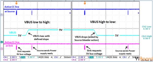
It is worth noting that "USB Power Delivery" includes not only power-related negotiation, other negotiations, such as those related to alternate modes, are performed using power protocol on standard CC line.
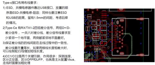
11 PCB layout requirements
Related
- Ultra-detailed USB Type-C pin signal and familiarity with PCB layout
- Diagram of relationship between PCB layout and EMC
- PCB design guidelines: safety regulations, layout and wiring, EMC, thermal design, process engineering.
- Should PCB trace angle be 90°? — Jumping guide to PCB layout pit
- USB trace layout experience, a painful lesson
- Detailed explanation of 3 classic topologies (with circuit diagrams and calculation formulas)
- Do you know layout requirements of some special devices in PCB design?
- With these two schematics, PCB design is easy!
- Common USB Interface Circuit Design Problems and Solutions
- Daniel's Summary: The details and experience of 30 PCB layouts are wonderful.
Hot Posts
 How to distinguish induction from leakage, we will teach you three tricks! Ordinary people can also learn super practical
- What is drowning in gold? Why Shen Jin?
- This is a metaphor for EMI/EMS/EMC that can be understood at a glance.
- How many types of pads have you seen in PCB design?
- Summary of Common PCB Repair Techniques
- What is three anti-paint? How to use it correctly?
- Knowing these rules, you will not get confused looking at circuit diagram.
- How to make anti-interference PCB design?
- Can diodes do this?