Archive
-
Super practical! The 10 Most Commonly Used Power Supply Design Formulas
Archive
1. Maximum Duty Cycle Dmax of MOSFET Switch: In formula: Vor is reflected voltage refracted from secondary side to primary side, when AC input is 220V, reflected voltage is 135V; VminDC - smallest constant voltage after rect...
2023-04-21【Archive】
View -
What is difference between 0 ohm resistors, inductors and magnetic balls for single point grounding?
One, 0 ohm resistance Basic Introduction: Analog and Digital Ground Single Point As long as it's ground, it must be connected together at end, and then enter ground. If they are not connected together, they will "float" and a volt...
2023-04-20【Archive】
View -
Why is starting current of motor large? After starting, current is again small?
Archive
How big is motor starting current? There are different opinions about how many times starting current of a motor exceeds rated current, and many of them are based on specific conditions. For example, more than ten times, 6-8 time...
2023-04-20【Archive】
View -
It suddenly dawned on me that a 0 ohm resistor can still be used like this
Archive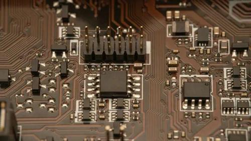
In our opinion, resistance should impede flow. What about a 0 ohm resistor? What kind of resistor do we need that can't stop current? Actually, 0 ohm resistors didn't show up at the beginning, and most 0 ohm resistors are ICs. T...
2023-04-19【Archive】
View -
Control Loop Design Solution, 5 steps to tell you
Archive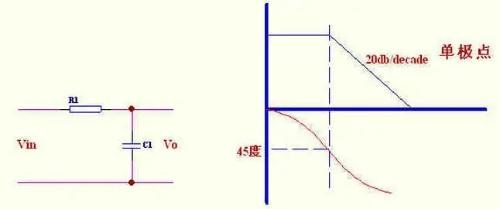
Introduction As an engineer, I interact with power supply design engineers every day. I have found that whether you are a veteran, a DIYer, or a beginner, you have almost no idea how to design a control loop. You mostly rely on ex...
2023-04-19【Archive】
View -
Does circuit diagram actually contain that much truth?
Archive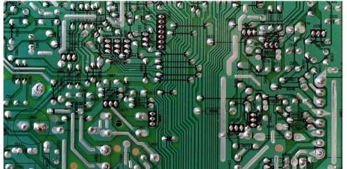
A wiring diagram is a wiring diagram of electronic components drawn using circuit component symbols. It details connection and direction of each component, a description of each pin, and some test data. Schematic, also known as "...
2023-04-19【Archive】
View -
A detailed explanation of three commonly used LED drive power schemes.
Archive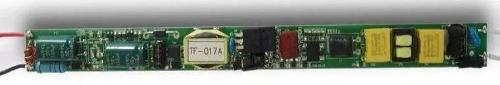
There are many types of LED power supplies, and quality and price of different power supplies vary greatly, which is also one of important factors affecting quality and price of product. LED drive power can generally be divided in...
2023-04-18【Archive】
View -
Should PCB trace angle be 90°? — Jumping guide to PCB layout pit
Archive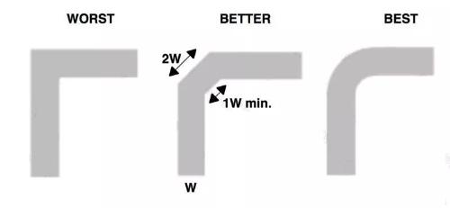
Now, whenever you open PCB layout guide of original SoC factory, you will always indicate corner angle of high-speed signal trace and say that high-speed signal should not be traced at a right angle, but at a 45 degree angle, roun...
2023-04-18【Archive】
View -
(Detailed long text) 7 ways to use diodes that engineers need to master
Archive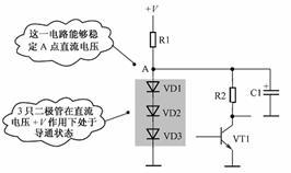
Introduction Many beginners are "familiar" with diodes. When they mention characteristics of a diode, they may blurt out its unidirectional conduction characteristics. When it comes to its application in circuits, first reaction ...
2023-04-18【Archive】
View -
3 MOSFET device selection rules that will teach you how to become a device selection wizard
Archive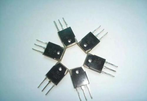
As saying goes, "people who don't think about long term should think about short term." Electronics design engineers before starting a project, at beginning of device selection, must carefully consider everything and choose most s...
2023-04-17【Archive】
View
Hot Posts
 How to distinguish induction from leakage, we will teach you three tricks! Ordinary people can also learn super practical
- What is drowning in gold? Why Shen Jin?
- This is a metaphor for EMI/EMS/EMC that can be understood at a glance.
- How many types of pads have you seen in PCB design?
- Summary of Common PCB Repair Techniques
- What is three anti-paint? How to use it correctly?
- Knowing these rules, you will not get confused looking at circuit diagram.
- How to make anti-interference PCB design?
- Can diodes do this?